Electric device for cam lock

An electric device and cam lock technology, which is applied in the field of combination locks, can solve the problems of high power consumption of electromagnets, stuck screws, and stress concentration, etc., and achieves easy processing and installation, tight electromechanical integration, and reduced stress concentrated effect

Inactive Publication Date: 2014-02-19
SHANGHAI BUDDY TECHONOLOGICAL
View PDF5 Cites 0 Cited by
  • Summary
  • Abstract
  • Description
  • Claims
  • Application Information

AI Technical Summary

Problems solved by technology

[0006] When encountering illegal strong unlocking, a large external force is directly transmitted to the lock tongue through the door handle or door bolt, and the lock tongue directly transmits the external force to the action part (iron mandrel) of the electromagnet (solenoid). Due to the line contact between the deadbolt and the head of the action part, the stress is very concentrated, which may easily cause damage to the action part and the electromagnet (solenoid) or the lock body;
[0007] The shape and size of the D-type lock tongue are relatively large, and the return tension spring also needs a large space to expand and contract. The two occupy a large internal space of the lock body, which makes it very difficult to reduce the volume of the lock body or add other components to the lock body.
[0008] In addition, in the prior art that is used to control the password lock of safe door, the electric device that adopts has following problems; It is a big disadvantage for the lock; if a two-way electromagnet is used, in addition to the complicated structure, a larger installation space is required
[0009] Using a motor, a mechanism that converts rotational motion into linear motion, and a screw and screw structure, due to the limitation of the internal space of the lock body, a small-volume high-speed motor is usually used, and the structure of the screw and screw used is also small in size. It is difficult to align the threaded rod and the threaded button at one time, and the threaded rod and threaded button will be stuck if they are not aligned, causing the motor to stall, which will damage the threaded rod and threaded button or damage the motor.

Method used


Image

  • Electric device for cam lock
  • Electric device for cam lock
  • Electric device for cam lock

Examples


Embodiment Construction

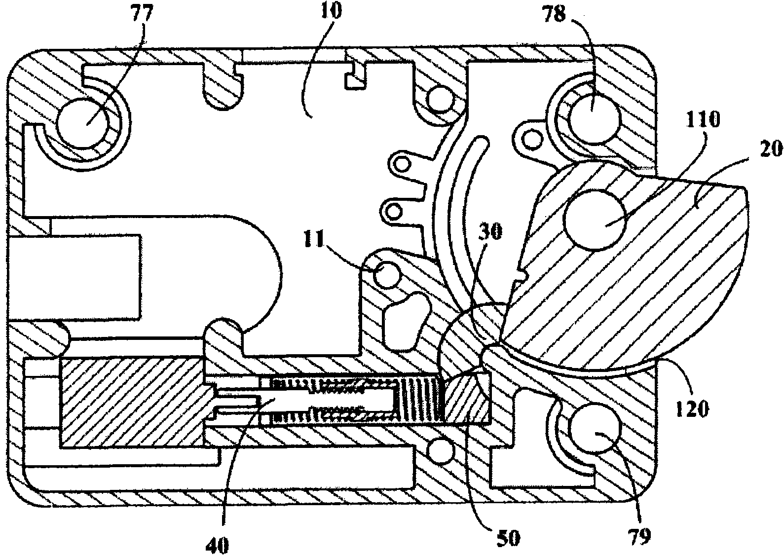
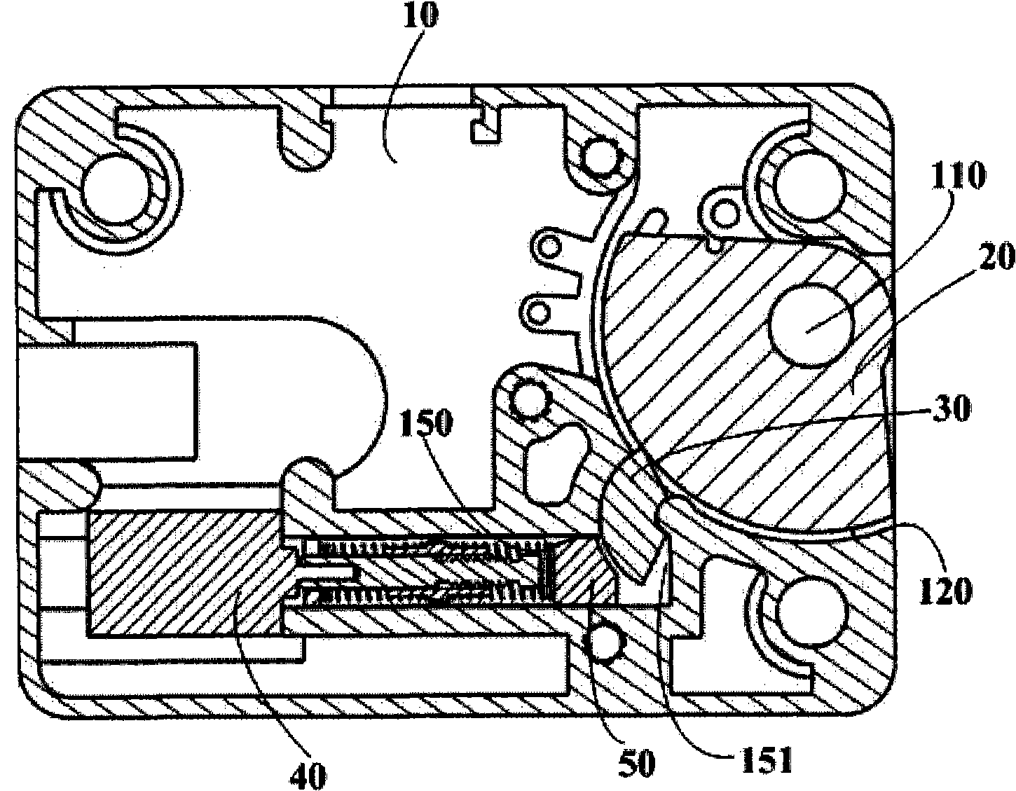
[0045] From figure 1 and figure 2 It can be seen that the fan-shaped dead bolt 20 is loaded into the shaft 110 in the lock box through the shaft hole 24 thereon, and can rotate around the shaft within a range of about 90 degrees. The height of the annular cylinder 31 of the block 30 and the height of the first slide groove 130 are substantially close to the plane thickness of the lock tongue 20, and the movement thereof is also carried out in the same plane.

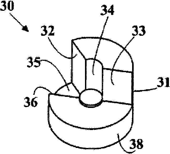
[0046] combine image 3 and Figure 4 , when assembling, the dead bolt 20 is first packed, and then the annular cylinder 31 of the block 30 is packed into the first chute 130 in the lock box, which is composed of a semi-cylindrical surface 131 and It is composed of an inner cylindrical wall surface 132 opposite to it, and the distance between the two is just the ring width of the annular cylinder 31 of the stopper 30, but the sliding fit relationship between them needs to be ensured. After the block 30 is loaded, th...


PUM


Abstract

The invention relates to an electric device for rotating a lock bolt, comprising a motor (41), a screw rod (42) coaxially connected with the motor and a back follower (50) which is connected with the crew rod and is rotated along with the motor to make linear movement. The electric device is characterized in that the back follower comprises a sleeve pipe (56) and a buckle (61), wherein the sleeve pipe (56) is matched and rotated along with the screw rod to make linear movement, the inner hole (55) of the sleeve pipe (56) is in sliding fit with the outside diameter of the screw rod (42), and two pinholes (43 and 44) which are axially perpendicular to the inner hole (55) of the sleeve pipe are arranged at the sleeve pipe (56); and two legs (63 and 64) of the buckle (61) are respectively caused to penetrate through the two pinholes (43 and 44) of the sleeve pipe and are in threaded fit with the screw rod (42), thereby causing the buckle (61) and the sleeve pipe (56) to make the linear movement along with the screw rod (42) during the rotation thereof.

Description

[0001] This application is a divisional application of a Chinese invention patent application with an application date of June 11, 2007, an application number of 200710041833.2, and a title of "A Cam Lock and Its Electric Device". technical field [0002] The invention relates to a combination lock, more specifically, to an electronic combination lock for a safe. Background technique [0003] In the prior art, the combination lock body used to control the safe door usually adopts a straight-in, straight-out square deadbolt or wedge-shaped deadbolt. In the normal state (locked state), the retraction of the deadbolt is limited, and the deadbolt hinders the door handle or the door bolt. The restriction on the retraction of the deadbolt is to enter the correct password on the safe password input device and be preset. After the predetermined program is confirmed, it is realized by actuating an electric device, and the reset of the deadbolt to the normal state (locked state) is ca...

Claims


Application Information

Patent Timeline
Patent Type & Authority Patents(China)
IPC IPC(8): E05B49/00E05B47/06E05B65/52
Inventor 袁梦笑
Owner SHANGHAI BUDDY TECHONOLOGICAL
Why Eureka
Try Eureka