
One-way fixed float valve plate

A technology of valve trays and trays, applied in the field of structural improvement of fixed valve trays, can solve problems such as spraying and back-mixing phenomena that cannot be completely resolved, and achieve the effects of good liquid flow distribution, pressure drop, and simple structure

Inactive Publication Date: 2009-07-15
张晓宏
View PDF2 Cites 1 Cited by
  • Summary
  • Abstract
  • Description
  • Claims
  • Application Information

AI Technical Summary

Problems solved by technology

However, due to the existence of two valve legs, the phenomenon of counter-spray and back-mixing cannot be completely solved

Method used


Image

  • One-way fixed float valve plate
  • One-way fixed float valve plate
  • One-way fixed float valve plate

Examples


Embodiment 1

[0022] The methanol-water rectification system adopts the one-way fixed valve tray of the present invention to transform the original fixed valve tray. The number of trays is 30, the diameter of the tower is 2400mm, the spacing between the plates is 450mm, the opening rate of the tray is 7.8%, the material is stainless steel, and the float valves are arranged in the forward direction of the regular triangle. The valve plate is rectangular, the length of the valve hole is 50mm, and the width is 20mm. The side view of the valve plate is a bottomless trapezoid. The angle between the valve leg and the plate plane is 30°. The position (front end) is 5mm from the tray plate. After being put into operation, the processing capacity has been increased by 10%, and the pressure drop of the tray has been reduced by 5%. It has been running stably for 2 years now.

Embodiment 2

[0024] The rectification tower of a certain factory was reformed. The original 50-layer F1 float valve was used, and now it is changed to the one-way valve tray of the present invention. The tower diameter is 3200mm, and the plate spacing is 450m. The opening ratio of the tray is 12.5%, and one-way fixed float valves are arranged on the tray, arranged in an isosceles triangle. The valve plate is diamond-shaped, the valve hole is 40m long and 15mm wide. The side view of the valve plate is a bottomless triangle. The angle between the valve leg and the plate plane is 30°. The position (front end) is 8mm from the tray plate. The intake air volume is 50000Nm3 / h. After the reconstruction of the rectification tower, the total separation efficiency is increased by 12%, the total pressure drop of the tray is reduced by 15%, and the phenomenon of pressure increase caused by dirty blockage during the original operation disappears.


PUM

PropertyMeasurementUnit
Lengthaaaaaaaaaa
Widthaaaaaaaaaa

Abstract

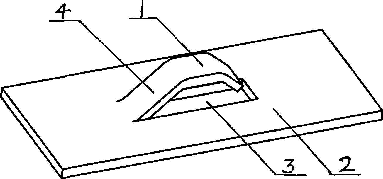
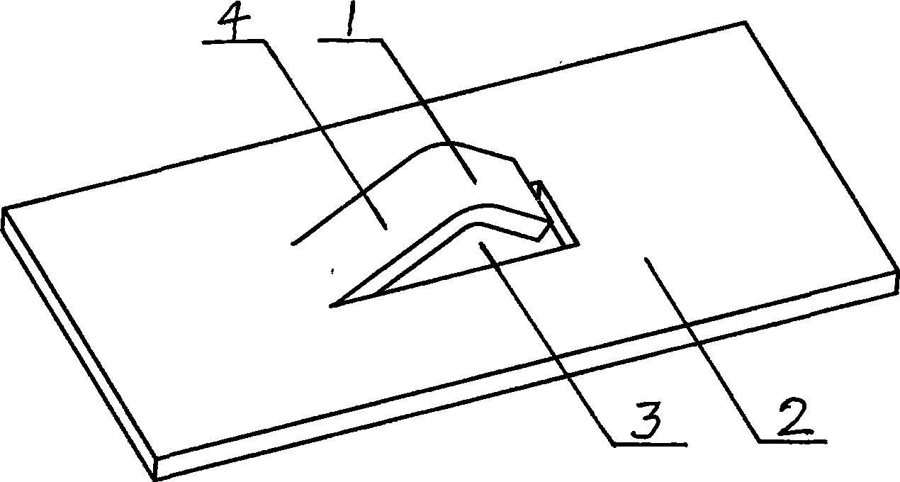
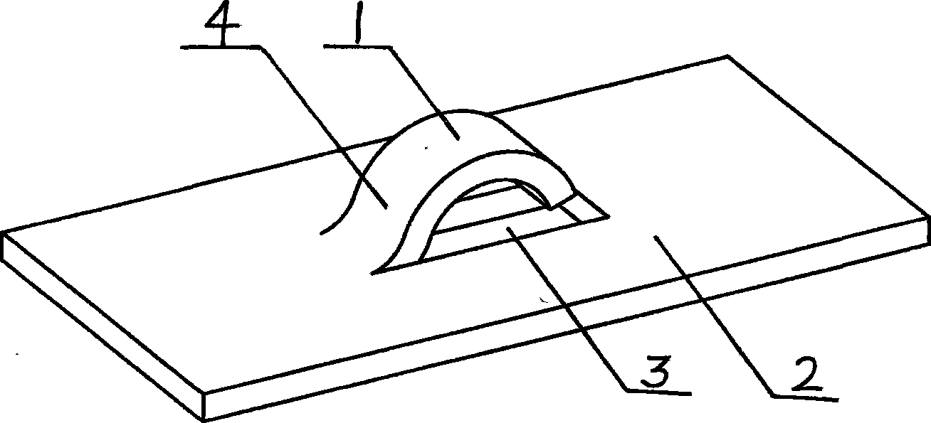
The invention discloses a column plate of a one-way fixed float valve, which comprises a valve opening (3), a valve plate (1) arranged on the column plate and a valve leg (4) connected to a column plate flat plate (2). The valve plate (1) is only provided with one valve leg (4), one surface of the valve plate (1) is fixed, and three surfaces of the valve plate (1) are hung; an included angle between the valve leg (4) and the column plate flat (2) is an acute angle; and the shape of the valve opening (3) on the column plate is identical with or similar to that of the valve plate (1). By adopting the structure, the invention improves the defects of excessive barrier generated by two valve legs of the traditional fixed valve and has low pressure drop and larger throughput, so that the mass transfer circumferential edge of the fixed valve is longer, the bubble is more uniform, and liquid on the column plate can be pushed towards the direction of an overflow weir by gas. Furthermore, the invention has the advantages of good flow distribution of the liquid on the surface of the column plate, higher separating efficiency, no movable piece and required connecting part, good dirt and block resistant property, simple structure, easy processing, and low production cost which is only 70- 80 percent of the common float valve column plate.

Description

technical field [0001] The invention relates to a structural improvement of a fixed valve tray in petroleum refining and chemical industry, in particular to a one-way fixed valve tray. Background technique [0002] The fixed valve tray has the advantages of large production capacity, high tray efficiency, low processing and maintenance costs, and is widely used in the petrochemical field. At present, there are mainly two types of fixed valve trays in the industry: circular fixed valves and strip-shaped fixed valves. It protrudes, and the edge opening is used as a gas phase channel. There is a valve leg connected to the tray at the front and back of the valve plate to support the valve plate. The angle between the valve leg and the plate plane is about 90 degrees. For the round valve, the gas outlet is a circular arc, and the gas ejected from the front half of the outlet has a certain pushing effect on the liquid flow on the plate, while the liquid ejected from the second ha...

Claims


Application Information

Patent Timeline
IPC IPC(8): B01D3/20
Inventor 耿皎张锋张晓宏张卫陈必扬
Owner 张晓宏
Learn More