
Frequency measuring instrument

A technology of frequency measurement and frequency, which is applied in the field of frequency measurement devices to achieve the effect of performance improvement

Inactive Publication Date: 2009-07-08
MITSUBISHI ELECTRIC CORP
View PDF2 Cites 7 Cited by
  • Summary
  • Abstract
  • Description
  • Claims
  • Application Information

AI Technical Summary

Problems solved by technology

[0011] To sum up, static frequency measurement devices will inevitably produce certain measurement errors, and power system control and protection devices that need to master high-speed, high-precision system frequencies are naturally limited.

Method used

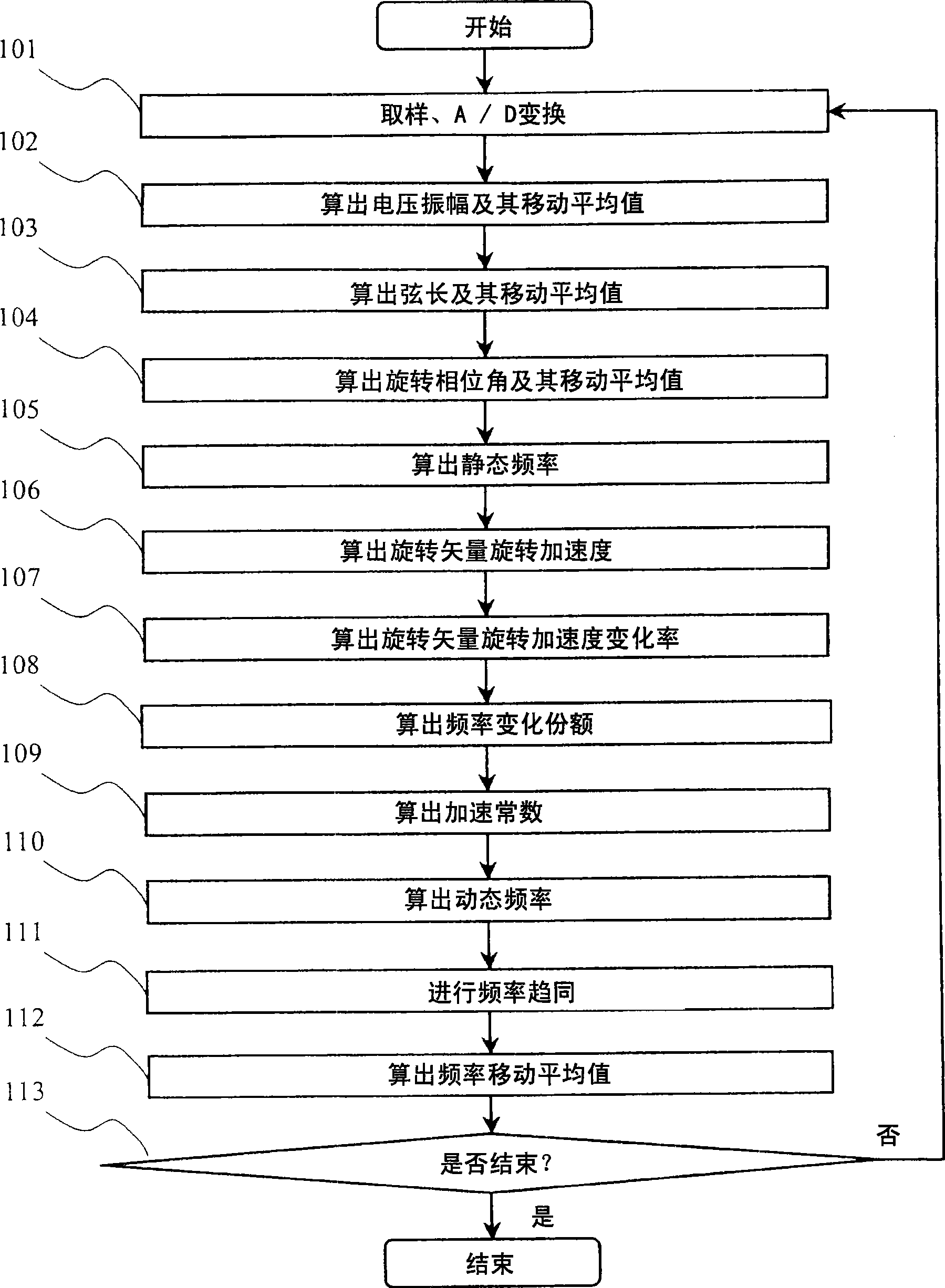
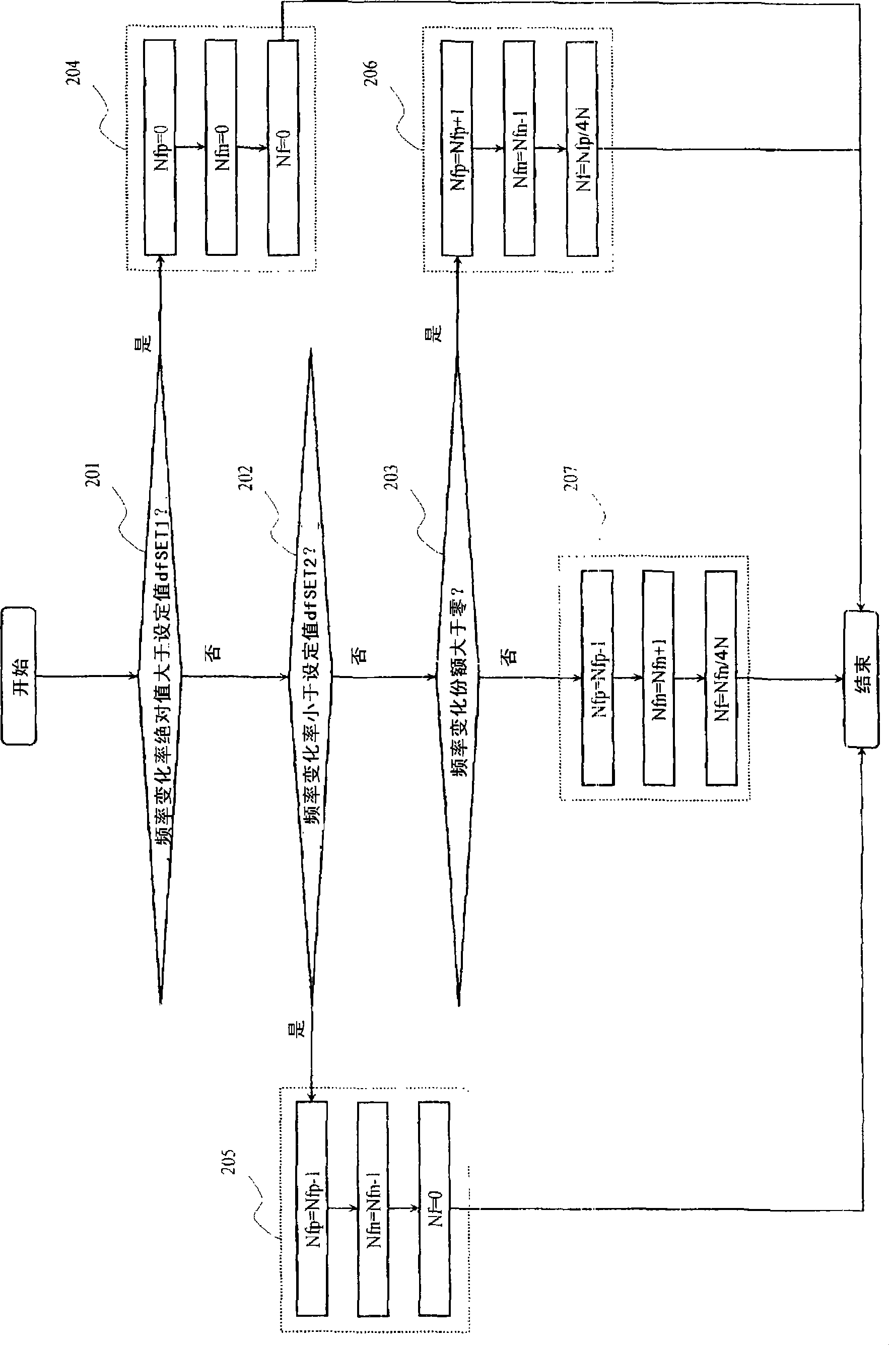

Image

  • Frequency measuring instrument
  • Frequency measuring instrument
  • Frequency measuring instrument

Examples


Embodiment approach 1

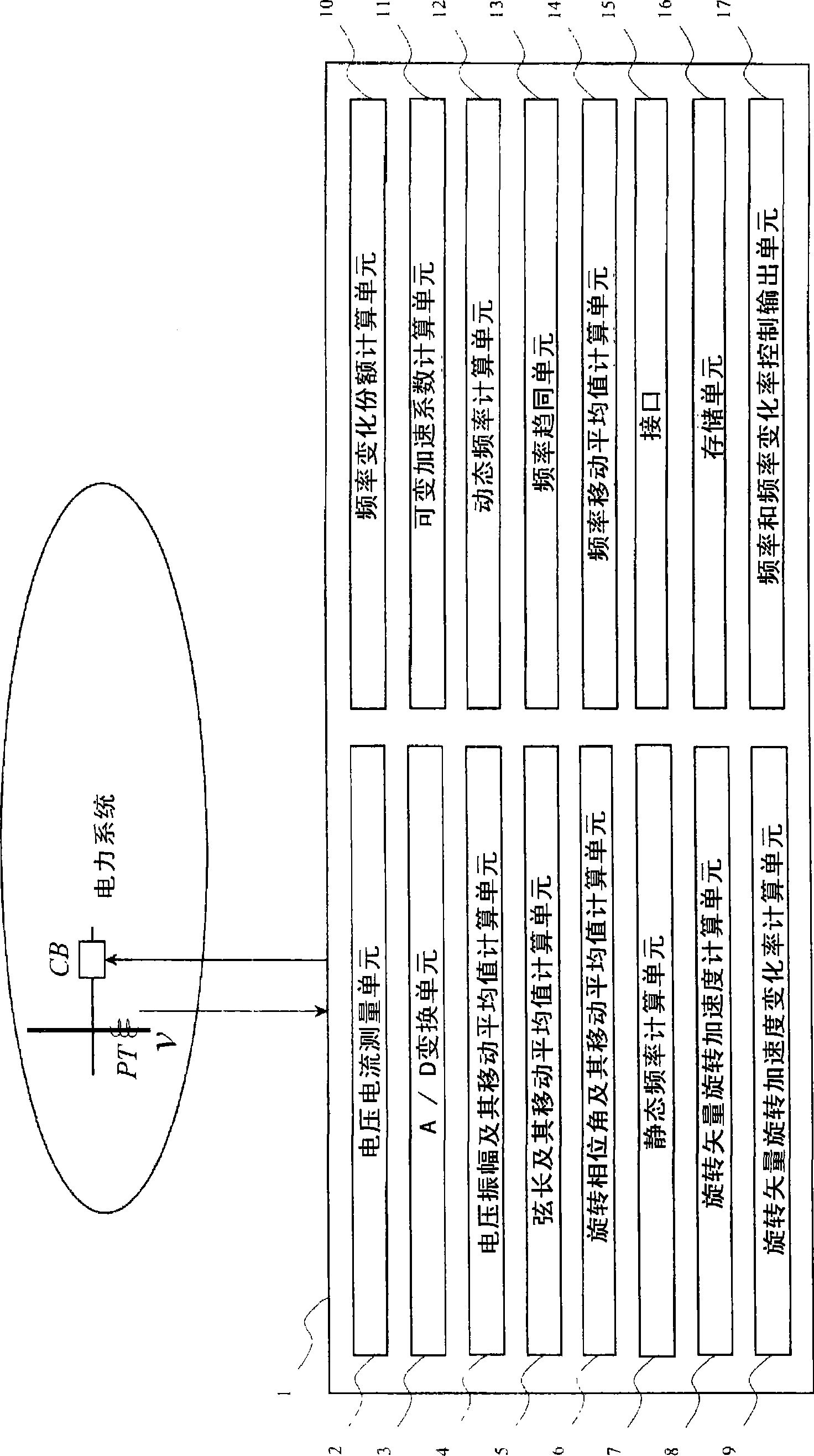
[0034] figure 1 The composition of the frequency measuring device of the present invention is shown. In the figure, 1 is a frequency measuring device, 2 is a voltage and current measuring unit for inputting time-series data of PT and CT, and 3 is an A / D conversion unit for converting time-series analog data into time-series digital data. Furthermore, when time-series digital data can be obtained, the voltage and current measurement means 2 and the A / D conversion means 3 can be omitted.

[0035] 4 is the voltage amplitude and its moving average calculation unit, which uses the instantaneous voltage value data of one cycle to calculate the voltage amplitude by the integration method, and uses the voltage amplitude calculation results of more than one cycle to average the voltage amplitude by the moving average method.

[0036] 5 is the chord length and its moving average calculation unit, which uses the voltage instantaneous value data of one cycle to calculate the chord lengt...


PUM


Abstract

The present invention provides a frequency measuring instrument in which the amplitude, string length and rotary phase angle of a voltage rotary vector are determined by integration method, rotary phase angle variation and the variation of rotary phase angle variation are further determined, variable acceleration coefficient is determined by distinguishing the frequency variation rate of every step, and then dynamic frequency is measured.

Description

technical field [0001] The present invention relates to a frequency measurement device using the amplitude, chord length and rotational phase angle of a voltage rotation vector. Background technique [0002] In recent years, as the power flow in the power system has become more complicated, reliable and high-quality power supply has been required, and in particular, the need for performance improvement of frequency measuring devices for protection devices in the power system has increased. [0003] In order to improve the control and protection performance of power systems, the inventors have proposed that a process based on rotation vectors in the complex plane is useful. This proposal is based on the basic method of representing an AC voltage in the complex plane as a vector rotating counterclockwise. For example, as described in Patent Document 1 (Japanese Unexamined Patent Application Publication No. 2004-361124), an existing frequency measurement device measures the vo...

Claims


Application Information

Patent Timeline
Patent Type & Authority Applications(China)
IPC IPC(8): G01R23/12G01R23/02
CPCG01R29/18G01R23/02G01R19/2513
Inventor 关建平
Owner MITSUBISHI ELECTRIC CORP
Learn More