Fast releasing apparatus used for rolling door

A rolling shutter door and quick release technology, applied in the field of rolling shutter doors, can solve the problems of difficult operation and maintenance, easy aging of batteries, complex structure, etc., and achieve the effect of eliminating mechanical connection, simple and compact structure, and easy to popularize and apply.

Inactive Publication Date: 2009-07-08
石峥嵘
View PDF0 Cites 0 Cited by
  • Summary
  • Abstract
  • Description
  • Claims
  • Application Information

AI Technical Summary

Problems solved by technology

[0003] 1. Each controller needs to be equipped with a battery, an inverter and an automatic switching circuit. The system cost is high and the user cannot accept it.
[0004] 2. The battery is easy to age, unable to meet the needs of long-term work, and often needs to be replaced
[0005] 3. High failure rate, difficult operation and maintenance
[0006] 4. The emergency guarantee time is not long. Even a new backup power supply can only guarantee power failure for two to three hours. After a period of use, it can only guarantee more than ten minutes, which cannot effectively prevent disasters.
[0007] Based on the above situation, the cost of the fire shutter controller with backup power is relatively high, the practicability is poor, there are many disadvantages, and the user resistance is strong
At present, the fire shutter controller without backup power supply is generally used. This kind of controller cannot link the fire shutter in the state of power failure, and cannot actually effectively protect the fire in the event of a fire.
Some controllers without backup power supply have complex structures and large volumes, which are inconvenient for installation and debugging, and their complex structures have brought hidden dangers to the accuracy and reliability of the controllers.

Method used


Image

  • Fast releasing apparatus used for rolling door
  • Fast releasing apparatus used for rolling door
  • Fast releasing apparatus used for rolling door

Examples


Embodiment Construction

[0049] The present invention will be described in further detail below in conjunction with the accompanying drawings and specific embodiments.

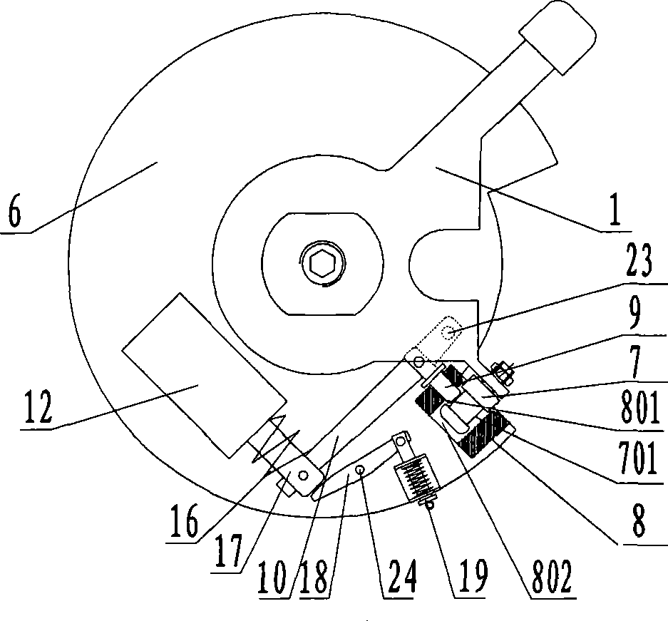
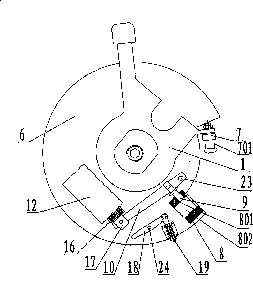
[0050] Such as Figure 1 to Figure 11 As shown, the present invention is used for the quick-release device of rolling shutter door, and it comprises mounting plate 6, drive plate 1, lifting mechanism and electric control start-up mechanism, and lifting mechanism comprises rotating rod 3 and positioning sleeve 4 that keeps fixed, and rotating rod 3 One end is fixed on the brake lever 14 top, and the other end links to each other with the drive plate 1, is provided with can drive the thread angle that brake lever 14 moves up and down between the rotating lever 3 and the positioning sleeve 4. The bottom end of the brake lever 14 is connected to the brake disc 15, and the motor brake lever 14 drives the brake disc 15 to clutch to form a clutch gap T. In this embodiment, the rotating rod 3 is a rotating screw, the positioning sleeve 4 is ...


PUM


Abstract

The invention relates to a quickly-releasing device for a rolling door, which comprises a mounting plate, a driving plate, a lifting mechanism and an electrically-controlled starting mechanism, wherein the lifting mechanism comprises a rotary rod and a fixed positioning sleeve. One end of the rotary rod is fixed on the top end of a brake lever, while the other end is connected with the driving plate. A screw thread lift angle which drives the brake lever to make up-and-down movement is arranged between the rotary rod and the positioning sleeve, one end of the driving plate is provided with a snib which is matched and connected with a lock cylinder fixed on the mounting plate. The lock cylinder is provided with a first slot radially for accommodating a bolt, and the lock cylinder is provided with a second slot axially for accommodating the snib. The snib is provided with a locking groove matched with one end of the bolt, and the other end of the bolt is connected with the electrically-controlled starting mechanism through a first connecting rod. The quickly-releasing device has the advantages of simple and compact structure, low cost, small volume, easy and simple operation, high control accuracy, high reliability, wide applicability, and the like.

Description

technical field [0001] The invention mainly relates to the field of rolling shutter doors, in particular to a quick-release device for rolling shutter doors. Background technique [0002] In order to realize the automatic release function of the fire shutter when it receives a fire alarm signal in a power failure state, the current common method is to equip the fire shutter controller with a battery and an inverter circuit. A starting voltage of 110V is generated to lower the fire shutter door. The main disadvantages of this system are: [0003] 1. Each controller needs to be equipped with a battery, an inverter and an automatic switching circuit. The system cost is high and the user cannot accept it. [0004] 2. The battery is easy to age and cannot meet the needs of long-term work, so it needs to be replaced frequently. [0005] 3. High failure rate and difficult operation and maintenance. [0006] 4. The emergency guarantee time is not long. Even a new backup power su...

Claims


Application Information

Patent Timeline
IPC IPC(8): E06B5/16E06B9/68E06B9/56
Inventor 李建民谭石荣石峥嵘
Owner 石峥嵘
Why Eureka
Try Eureka