Sheet material information detection apparatus, sheet material processing apparatus, and sheet material information detection method
A technology of information detection and sheet material, which is applied in the field of impact force mechanism and sheet material processing device, can solve the problem of not being able to fully obtain the characteristics of the dynamic behavior of the sheet material, and achieve the effect of improving measurement accuracy
- Summary
- Abstract
- Description
- Claims
- Application Information
AI Technical Summary
Problems solved by technology
Method used
Image
Examples
no. 1 approach
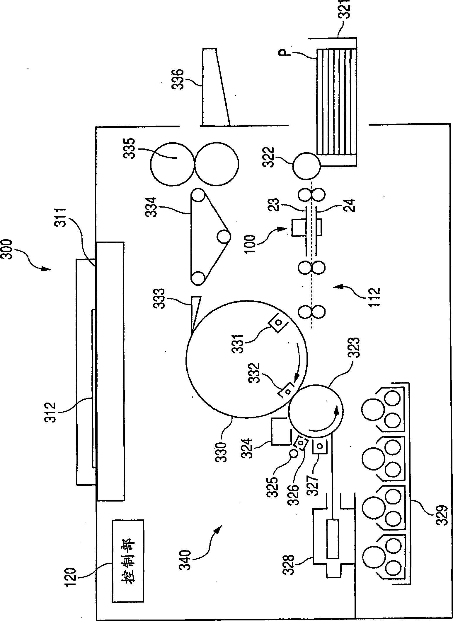
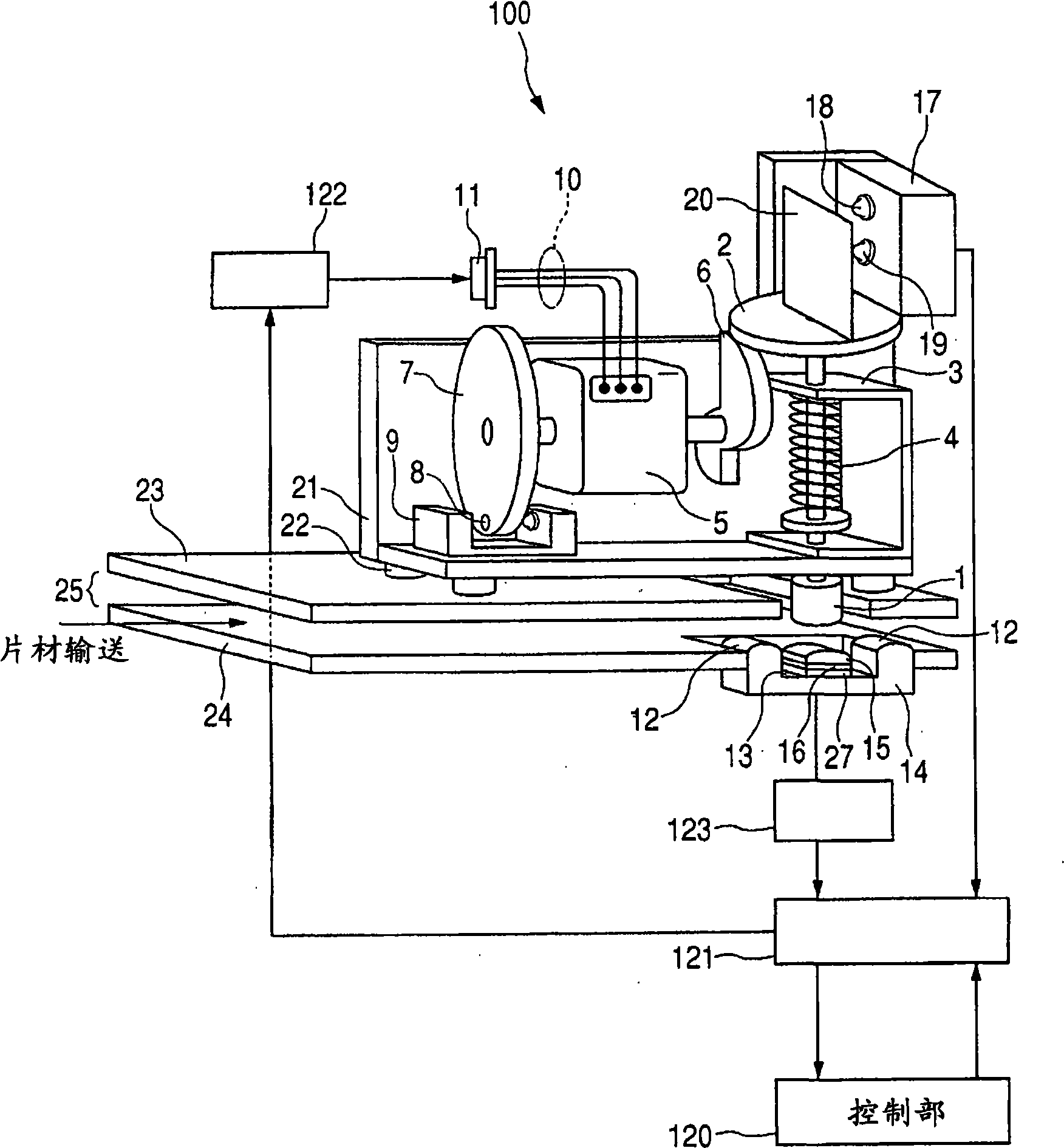
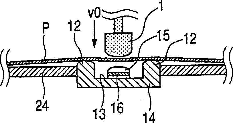
[0035] figure 1 is an explanatory view of the structure of the image forming apparatus. figure 2 is an explanatory view of the structure of the sheet information detection apparatus according to the first embodiment of the present invention. Figures 3A to 3D is an explanatory view showing a collision process of moving members. Figure 4 is a graphical representation of the results detected by the motion detector. Figure 5 is a flowchart showing the operation of the sheet information detection device.
[0036] Such as figure 1 As shown, the image forming apparatus 300 is a color copier for performing image formation on a sheet P by an image formation processing section 340 . The reading unit 311 reads image information of a color original 312 . The read information is converted into color signals corresponding to four colors of toners (cyan, magenta, yellow, and black).
[0037] On the other hand, the sheet P accommodated in the cassette 321 is sent to the conveyance...
no. 2 approach
[0101] Figure 6 is a flowchart of the control of the sheet processing apparatus according to the second embodiment of the present invention. Figure 7 It is a table for outputting sheet information using the measurement unit and piezoelectric element. In the second embodiment of the present invention, it will be described in reference figure 2 and Figure 4 Control in a case where the sheet information detection apparatus 100 described above is installed in a sheet processing apparatus other than the image forming apparatus 300 .
[0102] First, the sheet processing apparatus starts a sheet processing operation to start conveying the sheet (S21). Starting a sheet processing operation is performed by a user (operator) of the sheet processing apparatus pressing a start button on the apparatus main body, by sending a processing instruction from a peripheral device such as an external computer or a camera connected thereto, or the like.
[0103] Then, the operation of the she...
no. 3 approach
[0120] Figure 8 is an exemplary view of the structure of a sheet information detection apparatus according to a third embodiment of the present invention. The sheet information detection apparatus 200 according to the third embodiment of the present invention includes as its main components: a moving member 31 for colliding with the sheet; an acceleration unit for making the moving member 31 have a predetermined speed; a supporting member for the sheet; and a measuring unit for measuring the movement of the moving member 31 . In the third embodiment of the present invention, the moving member 31 is allowed to collide with the sheet through a rotational motion in which the moving member 31 is allowed to swing about the support 33 . Furthermore, for the measurement section 47, a transmission optical sensor that is less expensive than the laser Doppler velocimeter used in the first embodiment is employed. The measurement section 47 has a structure in which the light shielding ...
PUM
 Abstract
Description
Claims
Application Information
 - R&D
- Intellectual Property
- Life Sciences
- Materials
- Tech Scout
- Unparalleled Data Quality
- Higher Quality Content
- 60% Fewer Hallucinations
Browse by: Latest US Patents, China's latest patents, Technical Efficacy Thesaurus, Application Domain, Technology Topic, Popular Technical Reports.
© 2025 PatSnap. All rights reserved.Legal|Privacy policy|Modern Slavery Act Transparency Statement|Sitemap|About US| Contact US: help@patsnap.com


