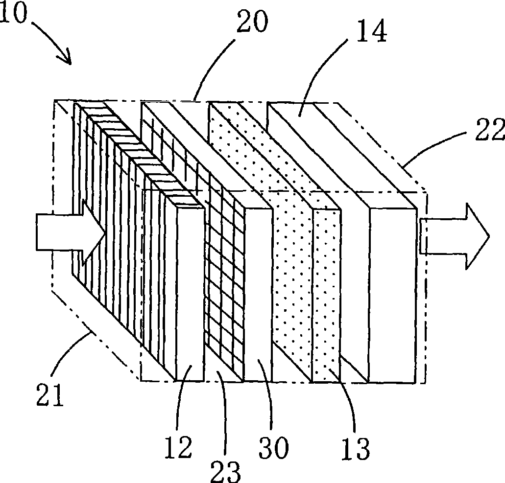
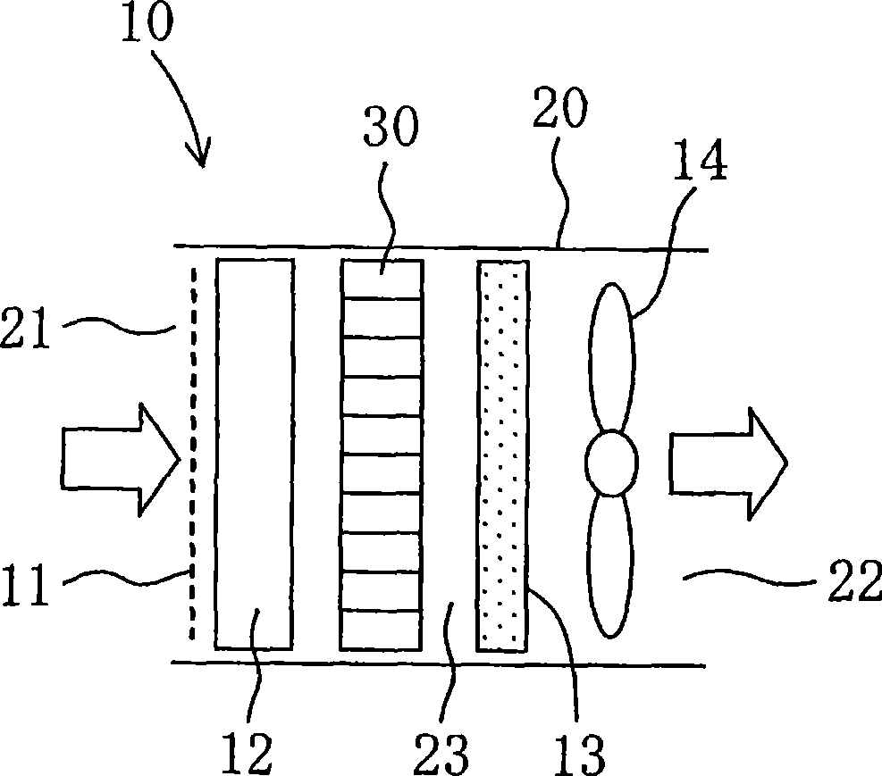
Dust collector
A technology of dust collection device and dust collection unit, which is applied in the direction of solid separation, external electrostatic separator, electrostatic separation, etc. It can solve the problems of small dust collection area, difficulty in miniaturization of the device, difficulty in seeking high performance, etc., to achieve collection The effect of increasing the dust area and increasing the dust collection area
- Summary
- Abstract
- Description
- Claims
- Application Information
AI Technical Summary
Problems solved by technology
Method used
Image
Examples
no. 2 approach
[0107] Next, a second embodiment of the present invention will be described in detail with reference to the drawings.
[0108] like Figure 6 As shown, in this embodiment, the dust collecting electrode 40 is made of conductive metal instead of both the dust collecting electrode 40 and the high voltage electrode 50 being made of conductive resin in the first embodiment.
[0109] That is, the dust collecting electrode 40 is formed of a thin metal plate such as stainless steel, and the high voltage electrode 50 is formed of a conductive resin as in the first embodiment.
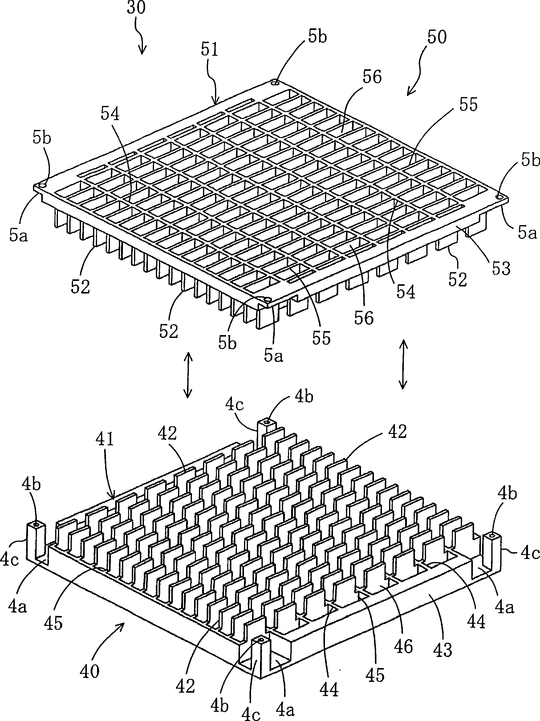
[0110] Like the first embodiment, the dust collecting electrode 40 is formed in a rectangular shape and includes a base part 41 and many protruding parts 42. Isolation part 45. Furthermore, the protruding member 42, the frame body 43, the vertical spacer 44, and the horizontal spacer 45 are each formed of a thin conductive metal plate.
[0111] As in the first embodiment, the protruding part 42 of the dust co...
no. 3 approach
[0115] Next, a third embodiment of the present invention will be described in detail with reference to the drawings.
[0116] like Figure 7 and Figure 8 As shown, in this embodiment, the corner portion of the tip of the protrusion member 52 of the high voltage electrode 50 is formed in an arc shape. Instead of forming the top corner of the protrusion member 52 of the high voltage electrode 50 at an acute angle in the first embodiment.
[0117] Specifically, the top corner of the protruding member 52 of the high voltage electrode 50 is formed in an arc shape when viewed from the end surface of the top end, and is also formed in an arc shape when viewed from the left and right sides, plan view, and bottom view, thereby forming a circular shape. Arc portion 52a.
[0118] According to this embodiment, since the tip corner portion of the protruding member 52 is configured as the arc portion 52a, residues such as burrs can be surely removed. As a result, abnormal discharge due...
no. 4 approach
[0121] Next, a fourth embodiment of the present invention will be described in detail with reference to the drawings.
[0122] like Figure 9 and Figure 10 As shown, in this embodiment, the charging unit 12 and the dust collecting unit 30 are integrally formed instead of the charging unit 12 and the dust collecting unit 30 being independently formed in the first embodiment.
[0123] Specifically, the charging unit 12 has a needle-shaped ionization electrode 12 a. The ionization electrode 12 a is integrally formed with the high voltage electrode 50 on the top end surface of the protrusion member 52 of the high voltage electrode 50 and extends forward. Moreover, the ionization electrode 12a is located inside the ventilation hole 46 of the dust collecting electrode 40, and is surrounded by the longitudinal spacer 44 and the transverse spacer 45 of the dust collection electrode 40, and a part of the longitudinal spacer 44 and the transverse spacer 45 constitute the opposite el...
PUM
 Abstract
Description
Claims
Application Information
 - R&D Engineer
- R&D Manager
- IP Professional
- Industry Leading Data Capabilities
- Powerful AI technology
- Patent DNA Extraction
Browse by: Latest US Patents, China's latest patents, Technical Efficacy Thesaurus, Application Domain, Technology Topic, Popular Technical Reports.
© 2024 PatSnap. All rights reserved.Legal|Privacy policy|Modern Slavery Act Transparency Statement|Sitemap|About US| Contact US: help@patsnap.com


