Rotation angle detector

A technology of rotation angle detection and rotation angle, which is applied in the direction of measuring devices, electric devices, and electric/magnetic devices to transmit sensing components, etc., can solve the problems of reduced degrees of freedom, large-scale devices, and increased gear diameters, etc., to achieve The effect of wide detection angle range and high degree of design freedom

Inactive Publication Date: 2012-10-10
FURUKAWA ELECTRIC CO LTD
View PDF2 Cites 1 Cited by
  • Summary
  • Abstract
  • Description
  • Claims
  • Application Information

AI Technical Summary

Problems solved by technology

[0007] However, in conventional rotation angle detection devices, the phase difference between the detection signals used to calculate the rotation angle of the rotation body is uniquely determined by the characteristics of the magnets or the gear ratio of each auxiliary rotation body, so there is a design gap. The problem of reduced degrees of freedom
In addition, in the conventional rotation angle detecting device, if the detection angle range of the rotation angle of the rotating body to be detected is to be expanded, the diameter of the gear must be increased, so there is a problem of increasing the size of the device.

Method used


Image

  • Rotation angle detector
  • Rotation angle detector
  • Rotation angle detector

Examples


Embodiment approach 1

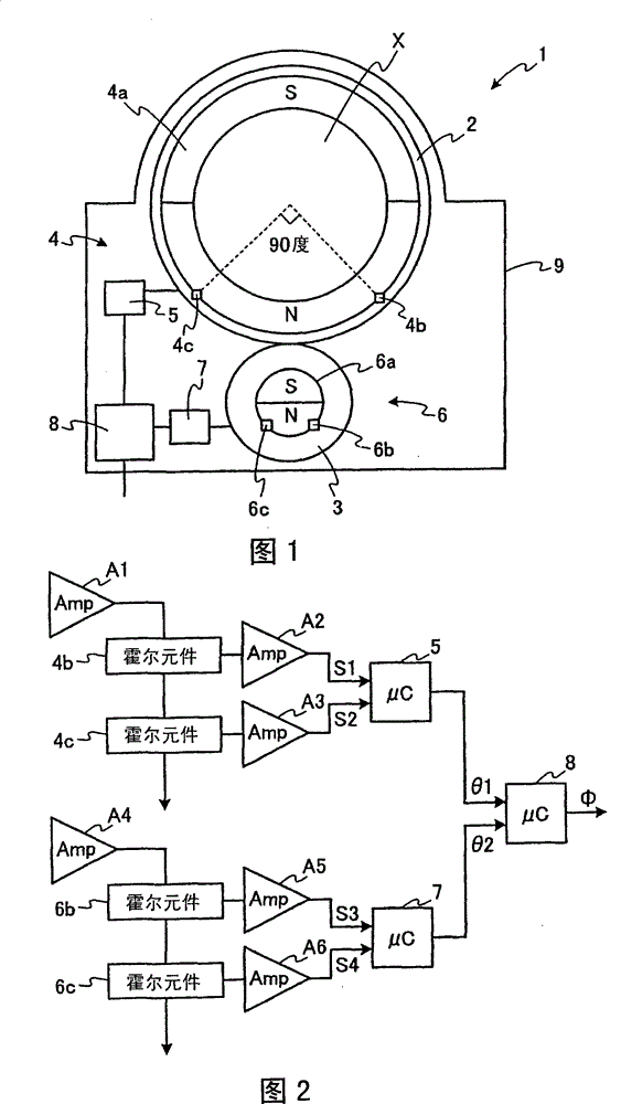
[0067] figure 1 It is a schematic cross-sectional view schematically showing the rotation angle detection device according to Embodiment 1 of the present invention. The rotation angle detection device according to Embodiment 1 detects the rotation angle of a steering shaft of an automobile as a rotating body to be detected.

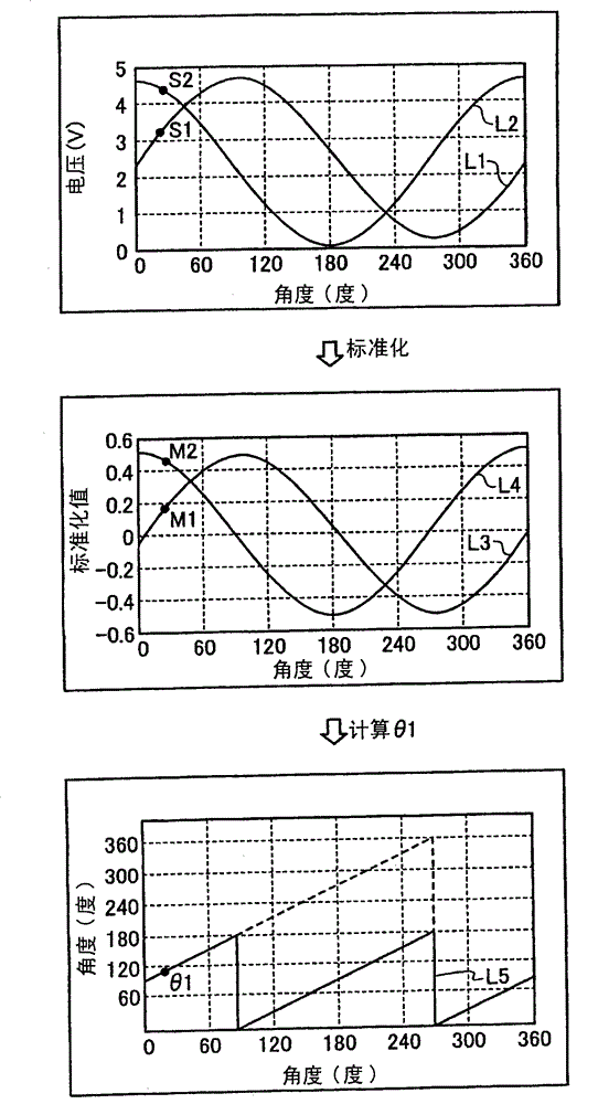
[0068] In addition, the rotation angle detecting device according to Embodiment 1 is an example in which the above-mentioned signals (A) to (D)

[0069] (C) Input signal from the main rotation detection mechanism processed in the signal processing mechanism

[0070] (D) The period of the input signal signal from the sub-rotation detection mechanism processed in the signal processing mechanism is set to be different from the period of one revolution of the main or sub-rotation body.

[0071] like figure 1 As shown, the rotation angle detection device 1 includes: the ring-shaped main gear 2 as the main rotating body, which is installed and fixed by inser...

Embodiment approach 2

[0126] Figure 8 It is a schematic cross-sectional view schematically showing a rotation angle detection device according to Embodiment 2 of the present invention. The rotation angle detection device of the second embodiment detects the rotation angle of the steering shaft of the automobile as the rotating body to be detected, as in the first embodiment.

[0127] In addition, the rotation angle detecting device according to Embodiment 2 is an example in which, among the above-mentioned (A) to (D) signals,

[0128] (A) Output signal of the main rotation detection mechanism

[0129] (B) Output signal of sub-rotation detection mechanism

[0130] The period of at least one of the signals is set to be different from the period of one revolution of the main rotator or the auxiliary rotator.

[0131] like Figure 8 As shown, the rotation angle detection device 101 includes: the ring-shaped main gear 102 as the main rotating body, which is installed and fixed by inserting the stee...


PUM


Abstract

A rotation angle detector for detecting a rotation angle of a detectable rotation body, comprises: a primary rotation body to be attached to the detectable rotation body and to rotate as integral with the detectable rotation body; a secondary rotation body to rotate as a predetermined rotation ratio for the primary rotation body; a primary rotation detection mechanism to output a signal to be varied periodically as corresponding to a rotation of the primary rotation body; a secondary rotation detection mechanism to output a signal to be varied periodically as corresponding to a rotation of the secondary rotation body; a signal processing unit to calculate the rotation angles of the primary and the secondary rotation bodies using the signals that the primary and the secondary rotation detection mechanisms output; and an operation processing unit to calculate the rotation angle of the detectable rotation body, based on the calculated rotation angle of the primary or of the secondary rotation body, and on a relative rotation angle between the primary and the secondary rotation body, wherein at least any one of the following signals (A) to (D) is designed to have a cycle as different from one cycle for one rotation of the primary rotation body or of the secondary rotation body; (A) an output signal of the primary rotation detection mechanism; (B) an output signal of the secondary rotation detection mechanism; (C) an input signal from the primary rotation detection mechanism to be processed at the signal processing unit; and (D) an input signal from the secondary rotation detection mechanism to be processed at the signal processing unit.

Description

technical field [0001] The invention relates to a rotation angle detecting device for detecting the rotation angle of a rotating body. Background technique [0002] Conventionally, there has been disclosed a rotation angle detection device that is attached to a rotating body such as a steering shaft of an automobile to detect the rotation angle of the rotating body. [0003] The conventional rotation angle device disclosed in Patent Document 1 includes a main rotating body that rotates together with the rotating body, and two sub rotating bodies that rotate in conjunction with the main rotating body. The main rotating body and the two auxiliary rotating bodies each have gears with different numbers of teeth, and the gears of each auxiliary rotating body mesh with the gears of the main rotating body. In addition, each sub rotating body has a magnet, and an AMR sensor (anisotropic magnetoresistive element) for detecting the magnetic field of each magnet is provided. Thus, th...

Claims


Application Information

Patent Timeline
Patent Type & Authority Patents(China)
IPC IPC(8): G01B7/30G01D5/18
Inventor 田中贤吾安倍文彦金东治
Owner FURUKAWA ELECTRIC CO LTD
Why Eureka
Try Eureka