Stator iron core construction for outer rotor permanent magnet motor and stator winding contra-wound method

A stator core and permanent magnet motor technology, applied in the direction of magnetic circuit shape/style/structure, electric components, manufacturing motor generators, etc., can solve the problem of reducing production efficiency, increasing production time, affecting the overall performance and consistency of the motor, etc. problems, to achieve the effects of improving production efficiency and product consistency, simplifying the closed slot process structure, and eliminating the influence of human factors

Active Publication Date: 2009-06-17
TIANJIN NAVIGATION INSTR RES INST
View PDF4 Cites 3 Cited by
  • Summary
  • Abstract
  • Description
  • Claims
  • Application Information

AI Technical Summary

Problems solved by technology

[0003] Although the above two stator winding winding methods have realized mechanized production, there are certain problems: the first method, the process leads to the growth of the winding coil end (invalid part), which affects the overall performance and consistency of the motor; at the same time , due to the adoption of two processes of winding and off-line, the production time is increased and the production efficiency is reduced; in addition, the coil is placed in the stator slot as a whole, which inevitably increases the slot width and aggravates the cogging effect of the motor
Although the second method solves some of the problems caused by the first method, it still has great limitations: First, it can only be applied to motors with a pitch of 1 slot, and for motors with a pitch other than 1 slot , the coil cannot be wound; in addition, it is only suitable for motors with few slots (usually not more than 10 teeth). When the number of stator teeth is large, the process complexity and man-hour consumption caused by single-tooth splicing and multiple wiring of windings are mass production. unacceptable

Method used


Image

  • Stator iron core construction for outer rotor permanent magnet motor and stator winding contra-wound method
  • Stator iron core construction for outer rotor permanent magnet motor and stator winding contra-wound method
  • Stator iron core construction for outer rotor permanent magnet motor and stator winding contra-wound method

Examples


Embodiment Construction

[0019] The present invention will be further described in detail below through the specific examples, the following examples are only descriptive, not restrictive, and cannot limit the protection scope of the present invention with this.

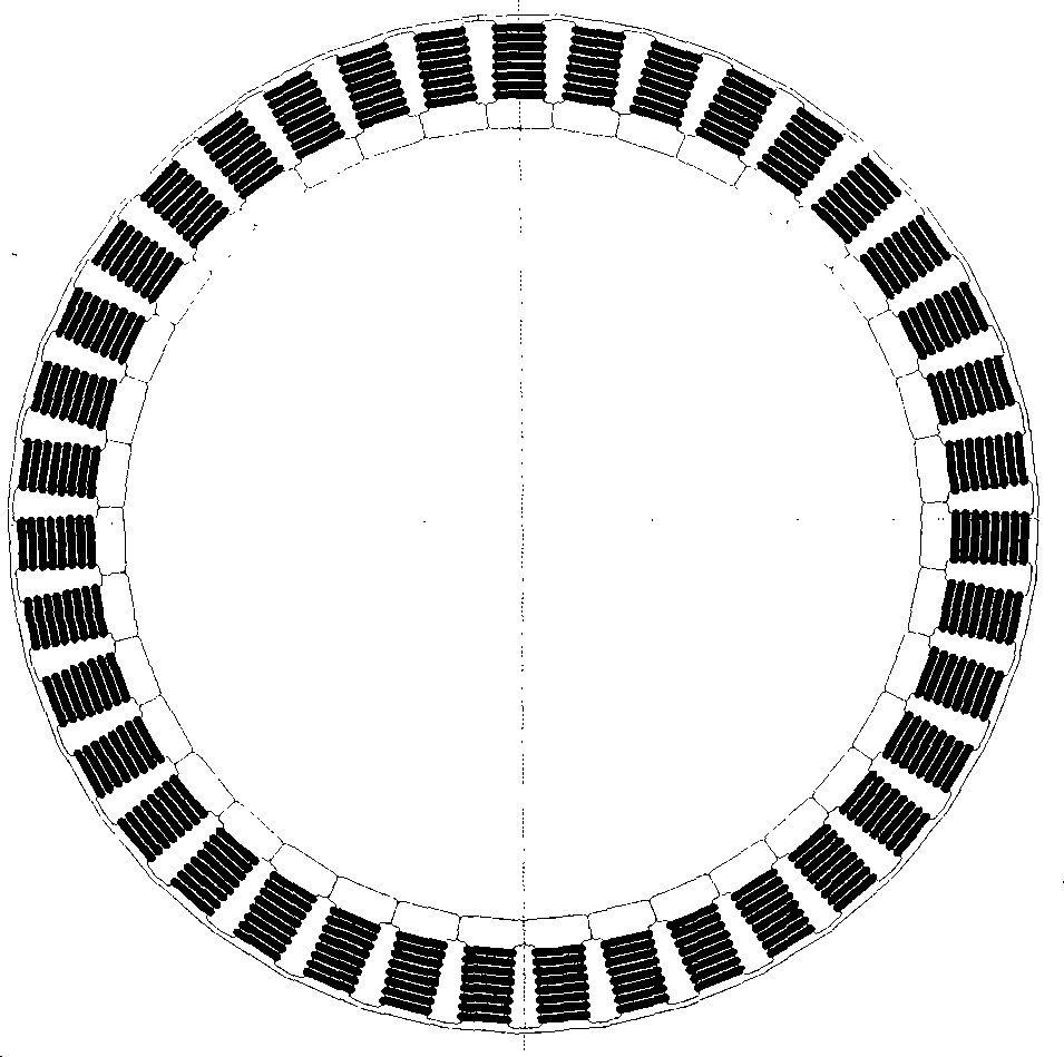
[0020] A stator core structure of an outer rotor permanent magnet motor, see figure 1 , figure 2 , image 3 , the stator core is a multi-rack structure with reverse slots, that is, the edges of the slots of the adjacent teeth of the stator core are connected by connecting bars 2, and the adjacent stator yokes 3 are made into the same slot gap , the winding 4 is rewound from the open stator yoke to the multi-rack stator tooth 1, and after being bent into a circular stator, the stator yoke is closed, and the air gap side of the stator teeth is connected to form a closed slot structure.

[0021] A method for rewinding a stator winding of an outer rotor permanent magnet motor, the steps of which are:

[0022] (1). The stator core connects th...


PUM


Abstract

The invention relates to an outer rotor permanent magnet motor stator iron core structure and a roll-back method of a stator winding, wherein a stator iron core thereof is a multi-tooth strip structure of an reverse slot, the edges of notches of the air gap sides of adjacent tooth portions of the stator iron core are made into connecting strips which are mutually connected, adjacent stator yoke portions are made into opening gaps, the self-opened stator yoke portions of the winding are rolled reversely on a multi-tooth strip stator tooth portion, the stator yoke portions are closed after being bent to a round stator, and the air gap sides of the stator tooth portion are located in a connecting state to form a closed slot structure. The invention has simple process and scientific and reasonable design, creates a novel stator structure, and reduces the slot effect. All production links of an outer rotor permanent magnet motor can achieve mechanized production, the effects of human factors are effectively eliminated, the production efficiency and the consistency of products are greatly increased, and the production cost is reduced.

Description

technical field [0001] The invention belongs to the field of motors, and relates to an outer rotor motor, in particular to a stator core structure of an outer rotor permanent magnet motor and a stator winding rewinding method thereof. Background technique [0002] In recent years, external rotor (or internal stator) motors have been widely used in various industries, and mass mechanized production has become a problem that must be solved. In the mass-produced external rotor permanent magnet motor, the winding of the stator winding is the most important problem in realizing mechanized production. At present, there are mainly two ways to realize the mechanized production of the stator of the outer rotor motor. 1. Use the mold to wind all the winding coils first, then remove the coils from the mold, and finally put them into the stator core slot one by one according to the order requirements; 2. When the winding pitch is 1 slot, the stator core can be divided into individual i...

Claims


Application Information

Patent Timeline
Patent Type & Authority Applications(China)
IPC IPC(8): H02K1/16H02K3/12H02K15/085
Inventor 周灏潘龙飞李德才李楠齐宇轩
Owner TIANJIN NAVIGATION INSTR RES INST
Why Eureka
Try Eureka