Device actuated by key operations
A technology of equipment and key pads, which is applied to electrical components, electrical switches, circuits, etc., can solve problems such as user discomfort, sweating, and reduced equipment control
- Summary
- Abstract
- Description
- Claims
- Application Information
AI Technical Summary
Problems solved by technology
Method used
Image
Examples
Embodiment approach 1
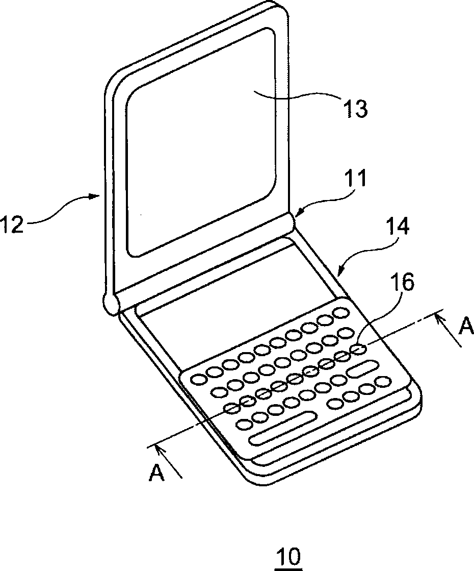
[0045] figure 1It is a schematic diagram showing the external configuration of a personal portable information terminal (PDA) 10 as the device of the first embodiment. In addition, in this embodiment, a PDA is used as an example of a device that operates by key operation, but for example, a digital camera (DSC), a digital video camera (DVC), an electronic dictionary, a portable device such as a notebook personal computer, Or a non-portable device such as a desktop PC.
[0046] Such as figure 1 As shown, PDA 10 has a structure in which display unit 12 and operation unit 14 are connected by hinge unit 11 , and display unit 12 and operation unit 14 are rotatably formed via hinge unit 11 . A display screen 13 composed of a liquid crystal display (LCD) or the like is provided on the display unit 12 . A plurality of keys 16 for instructing the execution of various operations of the PDA 10 or for inputting characters are arranged on the operation unit 14 .
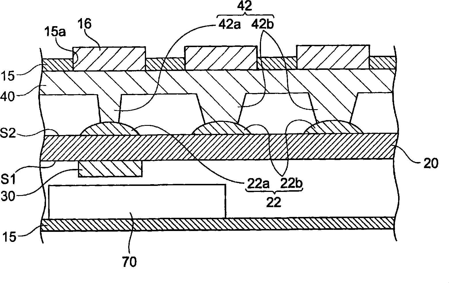
[0047] figure 2 yes...
Embodiment approach 2
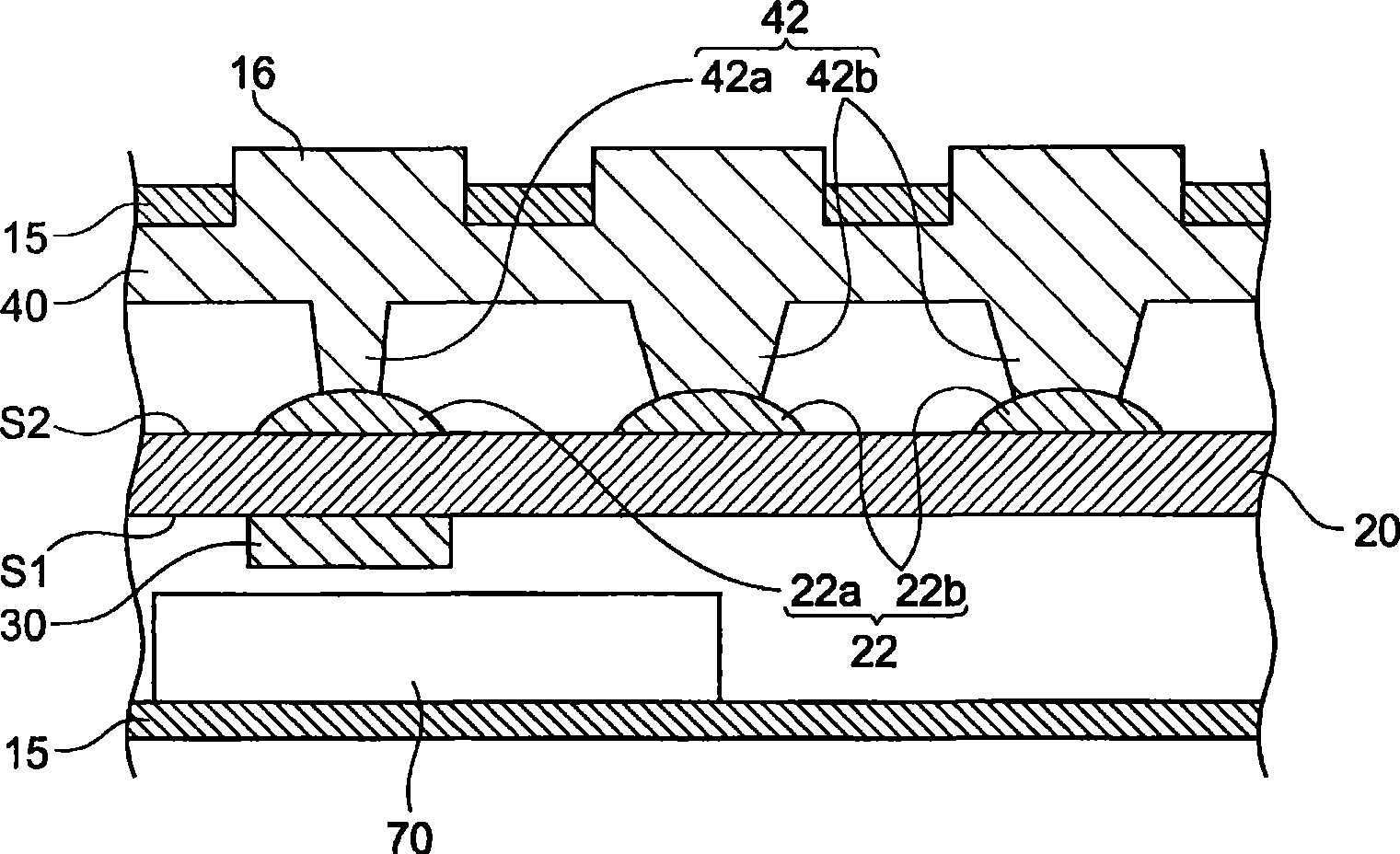
[0059] In the first embodiment described above, the contact area between the specific switch 22a located within a predetermined distance from the semiconductor element 30 and the protrusion 42a abutting on the specific switch 22a is made smaller than the other contact areas, but the following may be adopted. structure.
[0060] Image 6 It is a schematic partial sectional view of the device of this embodiment. The equipment of this embodiment and figure 1 Indicates the same as the PDA10, Image 6 is with figure 1 The section cut at the same position as the A-A line indicated in . in addition, Image 6 The casing 15 and the battery 70 are omitted.
[0061] Such as Image 6 As shown, in this embodiment, a gap 50 is provided between the specific switch 22a whose distance from the semiconductor element 30 in the surface direction of the substrate 20 is within a predetermined range and the protruding portion 42a protruding toward it, and the non-specific switch 22b and the p...
Embodiment approach 3
[0065] In this embodiment, in addition to the structure shown in Embodiment 1 or 2, the following structure is further provided.
[0066] 7(A) and (B) are schematic partial cross-sectional views of the device of this embodiment. FIG. 7(A) shows a state in which the structure of this embodiment is installed in the structure of Embodiment 1, and FIG. 7(B) shows a state in which the structure of this embodiment is installed in the structure of Embodiment 2. The device of this embodiment, and figure 1 The PDA10 represented in is identical, and Fig. 7 (A), (B) are in and figure 1 The section cut at the same position as the A-A line indicated in . In addition, the casing 15 and the battery 70 are omitted in FIG. 7 .
[0067] As shown in FIG. 7(A), in this embodiment, the contact area of the specific switch 22a and the protruding portion 42a protruding toward it is smaller than other contact areas, or as shown in FIG. A gap 50 is provided between the protruding portion 42a prot...
PUM
 Abstract
Description
Claims
Application Information
 - R&D Engineer
- R&D Manager
- IP Professional
- Industry Leading Data Capabilities
- Powerful AI technology
- Patent DNA Extraction
Browse by: Latest US Patents, China's latest patents, Technical Efficacy Thesaurus, Application Domain, Technology Topic, Popular Technical Reports.
© 2024 PatSnap. All rights reserved.Legal|Privacy policy|Modern Slavery Act Transparency Statement|Sitemap|About US| Contact US: help@patsnap.com


