Heat medium annular distributor with guiding blade for improving flow distribution
A technology of guide vanes and distributors, applied in the direction of indirect heat exchangers, heat exchanger types, chemical instruments and methods, etc.
- Summary
- Abstract
- Description
- Claims
- Application Information
AI Technical Summary
Problems solved by technology
Method used
Image
Examples
Embodiment 1
[0140] like Figure 4 As shown, an annular distributor with an annular slit layer and first type guide vanes and a reactor with the same annular distributor were fabricated. The annular distributor and reactor were set to meet the following dimensions.
[0141] Ring distributor width 520:400mm
[0142] Ring distributor height 510:600mm
[0143] Annular slit layer: single slit layer
[0144] Number of slits: 60
[0145] Width of each slit: 72.43mm
[0146] Height of each slit: 300mm
[0147] The starting point of the first type guide vane (the end of the first vertical baffle is in the direction of the outer circumference): 1000mm from the inner circumference to the outer circumference
[0148] The height of the first type guide vane: 600mm (same height as the annular distributor)
[0149] Number of guide vanes of the first type: 4
[0150] Shut-off plate: 1, relative to the central axis of the opening
[0151] Reactor diameter: 4150mm
Embodiment 1
[0153] Except for the first type guide vane and shut-off plate, the annular distributor and reactor are manufactured with the same specifications as in Example 1.
[0154] Experiment 1: Measurement of flow distribution in an annular distributor
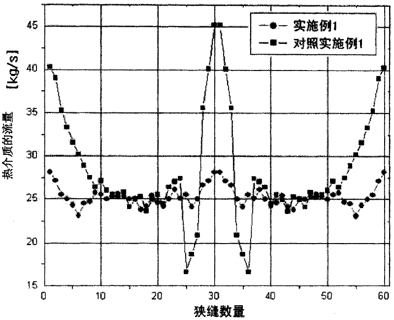
[0155] During the catalytic gas phase oxidation in the reactor manufactured according to Example 1 and Comparative Example 1, the flow distribution of the heat medium according to the slit was measured, and the results were as follows Figure 18 shown.
[0156] refer to Figure 18 , in the annular distributor equipped with the first type guide vanes of the present invention (Example 1), the flow rate of the heat medium is basically uniform and there is no significant difference due to the position of the slit. On the contrary, in the annular distributor without the first type guide vanes (comparative example 1), the flow rate of some slits (slot numbers 25 to 36) provided adjacent to the heat medium supply duct showed a decrease due...
Embodiment 2
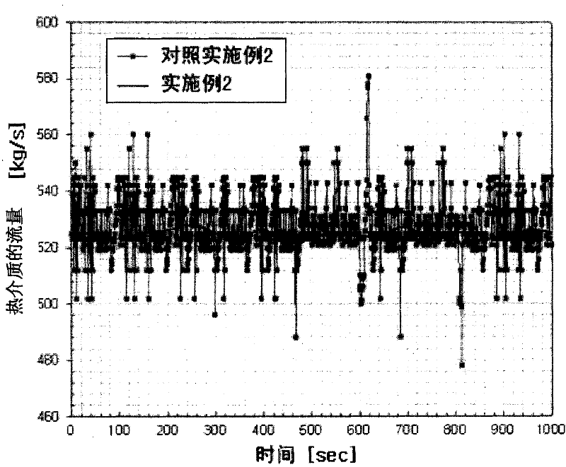
[0159] like Figure 7 The shown annular distributor with slotted layers and guide vanes of the second type and a reactor with the same annular distributor were fabricated. The annular distributor and reactor were set to meet the following dimensions.
[0160] The diameter of the slit layer: 4150mm
[0161] The height of the slit layer: 300mm
[0162] The width of the slit in the slit layer: 72.43mm
[0163] Distribution of slits in the slit layer: 6° (the angle is defined by two adjacent slits relative to the center of the slit layer circle)
[0164] The width of the duct of the ring distributor: 400mm
[0165] The shape of the second type guide vane: triangular prism
[0166] The length of the second type guide vane: 1000mm
PUM
 Abstract
Description
Claims
Application Information
 - R&D
- Intellectual Property
- Life Sciences
- Materials
- Tech Scout
- Unparalleled Data Quality
- Higher Quality Content
- 60% Fewer Hallucinations
Browse by: Latest US Patents, China's latest patents, Technical Efficacy Thesaurus, Application Domain, Technology Topic, Popular Technical Reports.
© 2025 PatSnap. All rights reserved.Legal|Privacy policy|Modern Slavery Act Transparency Statement|Sitemap|About US| Contact US: help@patsnap.com


