
Mold for crack-containing bolting test

A technology of cracks and molds, which is applied in the field of molds with cracks and anchor tests, can solve the problems of inability to effectively simulate the effect of anchor rods on crack reinforcement and crack prevention, the cumbersome process of making test specimens, and the inability to firmly fix anchor rods, etc. Achieve the effect of simple structure, low cost and convenient processing

Inactive Publication Date: 2010-12-08
SHANDONG UNIV
View PDF0 Cites 0 Cited by
  • Summary
  • Abstract
  • Description
  • Claims
  • Application Information

AI Technical Summary

Problems solved by technology

At present, there are very few types of molds used to make rock-like materials or similar materials containing cracks and anchoring specimens, and the few molds are relatively complicated. On the one hand, the mold itself has complicated manufacturing processes and high processing costs On the other hand, the process of making test specimens is cumbersome, inconvenient to use, labor-intensive and time-consuming, and the anchor cannot be firmly fixed, and the effect of the anchor on crack reinforcement and crack arrest cannot be effectively simulated.

Method used


Image

  • Mold for crack-containing bolting test
  • Mold for crack-containing bolting test
  • Mold for crack-containing bolting test

Examples


Embodiment Construction

[0035] The present invention will be further described below in conjunction with the accompanying drawings and embodiments.

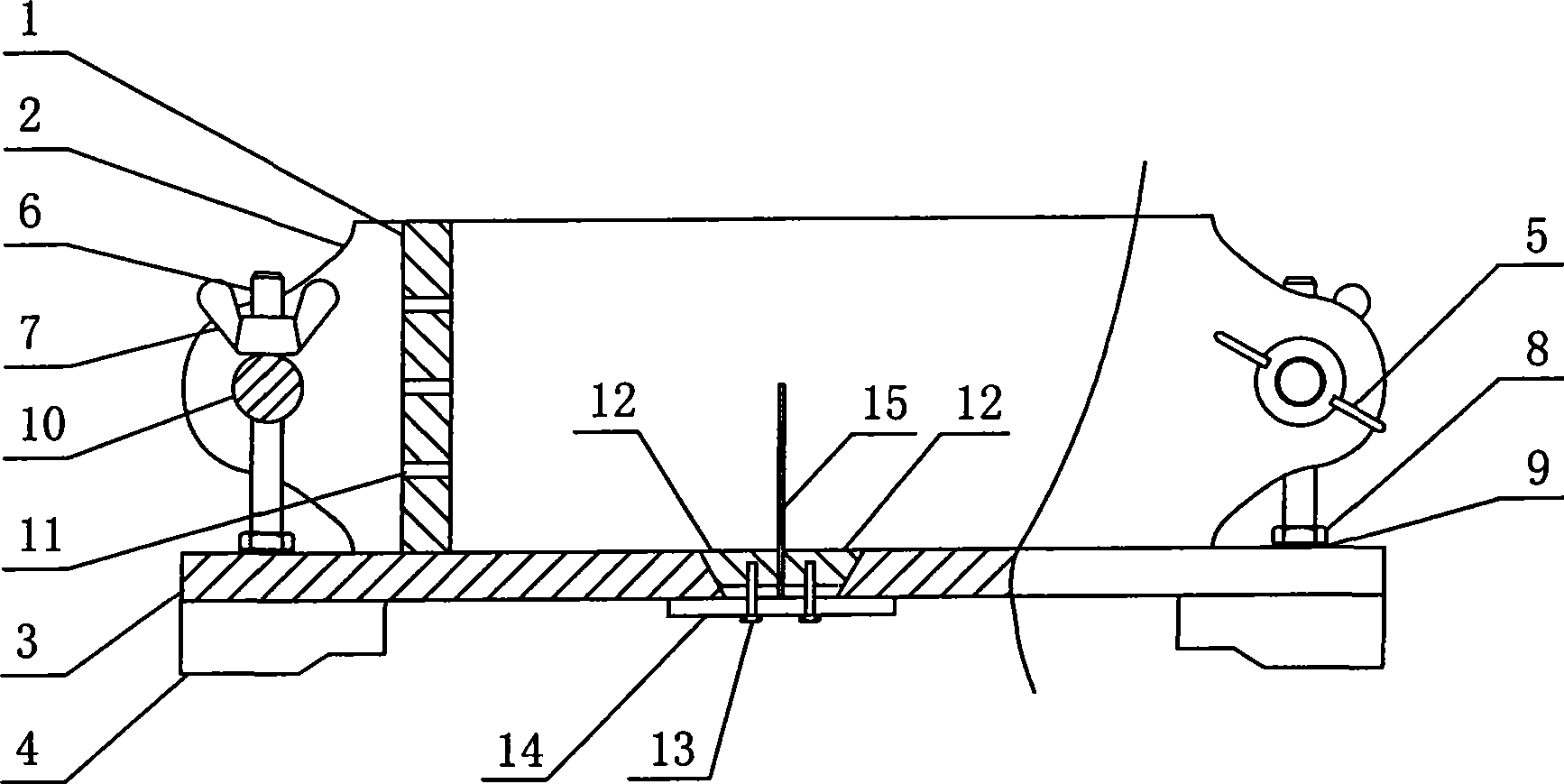
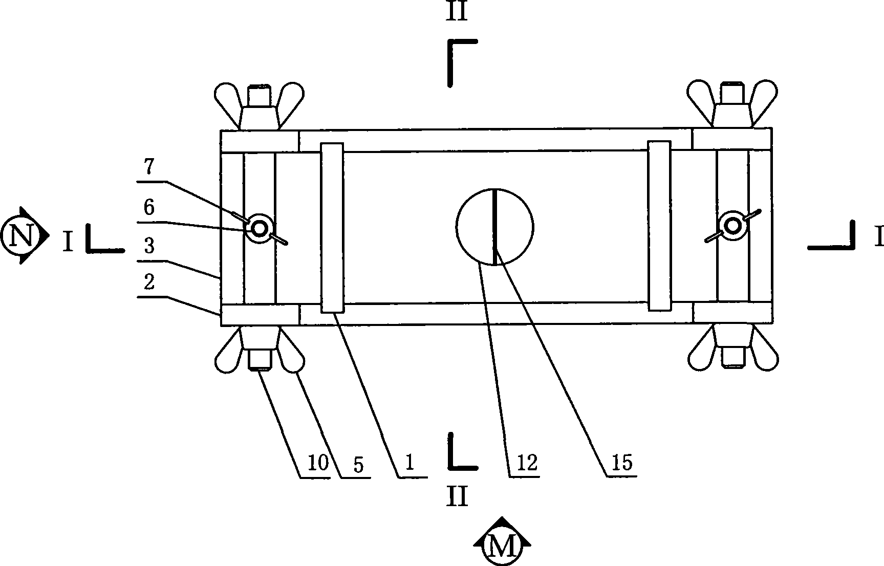
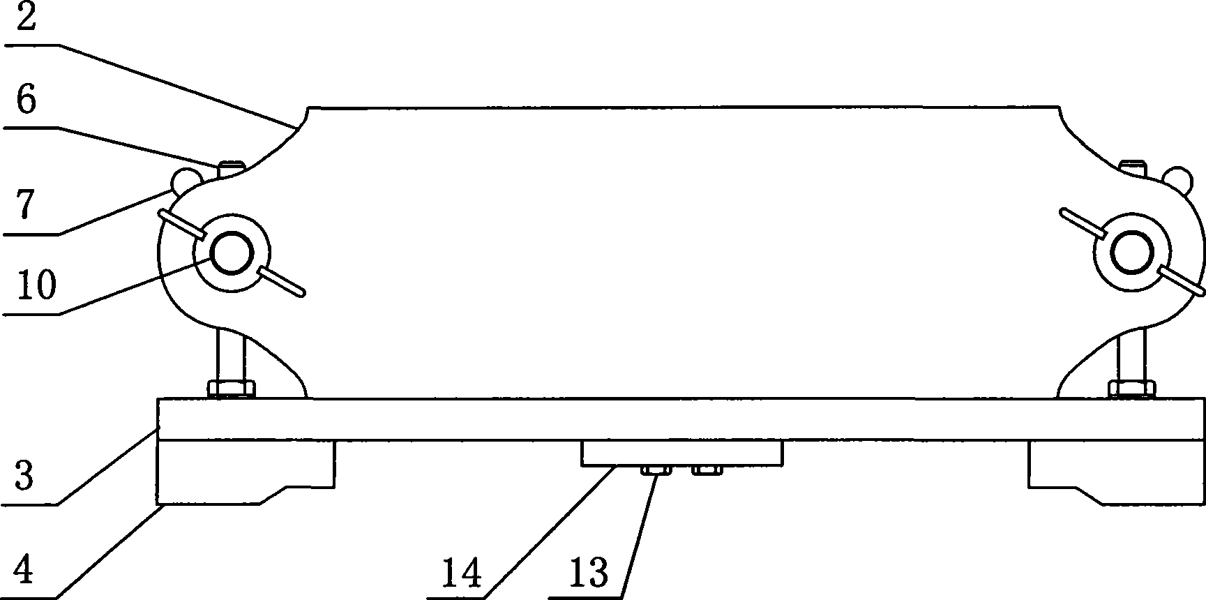
[0036] Figure 1-14 Among them, the bottom plate 3 is provided on the base 4, and the side plate 2, the end plate 1 and the vertical connecting rod 6 are vertically arranged on the bottom plate 3, and the two end plates 1 are vertically inserted between the two ends of the two side plates 2 respectively. , together form a frame with an upper opening, and two vertical connecting rods are respectively arranged between the two side plates 2 outside the two ends of the frame. The rods 10 are connected; the center of the bottom plate 3 is provided with a fixed slit device, and a plastic sheet 15 is provided on the fixed slit device.

[0037] Longitudinal grooves 16 and end holes 17 are symmetrically arranged on the side plate 2 , and both ends of the end plate 1 are placed in the longitudinal grooves 16 .

[0038] The end plate 1 is provided with several b...


PUM


Abstract

The invention relates to a mould used for a crack-contained anchored test. The mould comprises a base seat; the base seat is provided with a base plate; side plates, end plates and vertical connecting rods are arranged on the base plate; the two end plates are vertically inserted and connected between the two ends of the two side plates respectively to form a frame body that is provided with an opening at the upper part; the two vertical connecting rods are arranged between the two side plates outside the two ends of the frame body respectively; the two side plates are connected by horizontalconnecting rods that are vertically connected with the vertical connecting rods; the center of the base plate is provided with a crack fixed device; the crack fixed device is provided with plastic thin slices. When in use, after crack and anchor rods are fixed, each screw nut is tightly fastened, semi-solid state rock-like materials or similar materials are casted into the mould of the frame bodyand then fully vibrated. Then after being maintained, the mould is dismounted. When the mould is dismounted, the screw nut A on the side plate is loosened firstly; and the side plates are dismounted;then a device fixing the crack at the bottom is dismounted; finally, the base plate and the end plates are dismounted. The invention has the advantages that the structure is simple, the cost is low, the assembly and dismounting are convenient, the efficiency is high, etc.

Description

technical field [0001] The invention relates to a test mold, in particular to a mold for an indoor test with a crack and an anchor test. Background technique [0002] In energy development, mining and cutting slopes, there are joint surfaces of various shapes and sizes, and the existence of these joint surfaces strongly affects and restricts the behavior of rock mass. The mechanical behavior of rock mass under load is actually a comprehensive reflection of its internal structural plane. Numerous rock mass engineering practices at home and abroad have shown that the instability of rock mass engineering is mostly caused by the expansion of defects such as internal joints and cracks. In order to limit the deformation and failure of rock mass, anchor rods are commonly used in rock mass engineering for reinforcement. A large number of bolt reinforcements are used in mine roadways, railway tunnels and various underground projects in China. The reinforcement effect of bolts is v...

Claims


Application Information

Patent Timeline
Patent Type & Authority Patents(China)
IPC IPC(8): G01N3/00G01N33/00E21D9/14
Inventor 张宁李术才李明田杨磊刘钦刘人太
Owner SHANDONG UNIV
Learn More