Physical gas-phase deposition chamber gastightness detecting method
A technology of physical vapor deposition and air tightness detection, which is applied in the direction of using liquid/vacuum degree to measure liquid tightness, and using electrical devices to test fluid tightness, etc. It can solve the changes in PVD deposition chamber environment and production conditions, etc. Problems, to achieve the effect of reducing quantity and reducing consumption
Inactive Publication Date: 2009-06-17
SEMICON MFG INT (SHANGHAI) CORP
View PDF1 Cites 0 Cited by
- Summary
- Abstract
- Description
- Claims
- Application Information
AI Technical Summary
Problems solved by technology
[0008] Although the above method can be used to detect abnormal operation of the PVD deposition chamber in time, after the gas discharge in the vacuum is excited, it is easy to cause changes in the environment in the PVD deposition chamber, that is, it is easy to cause changes in production conditions.
Method used
View moreImage
Smart ImageViewing Examples
Examples
no. 1 example
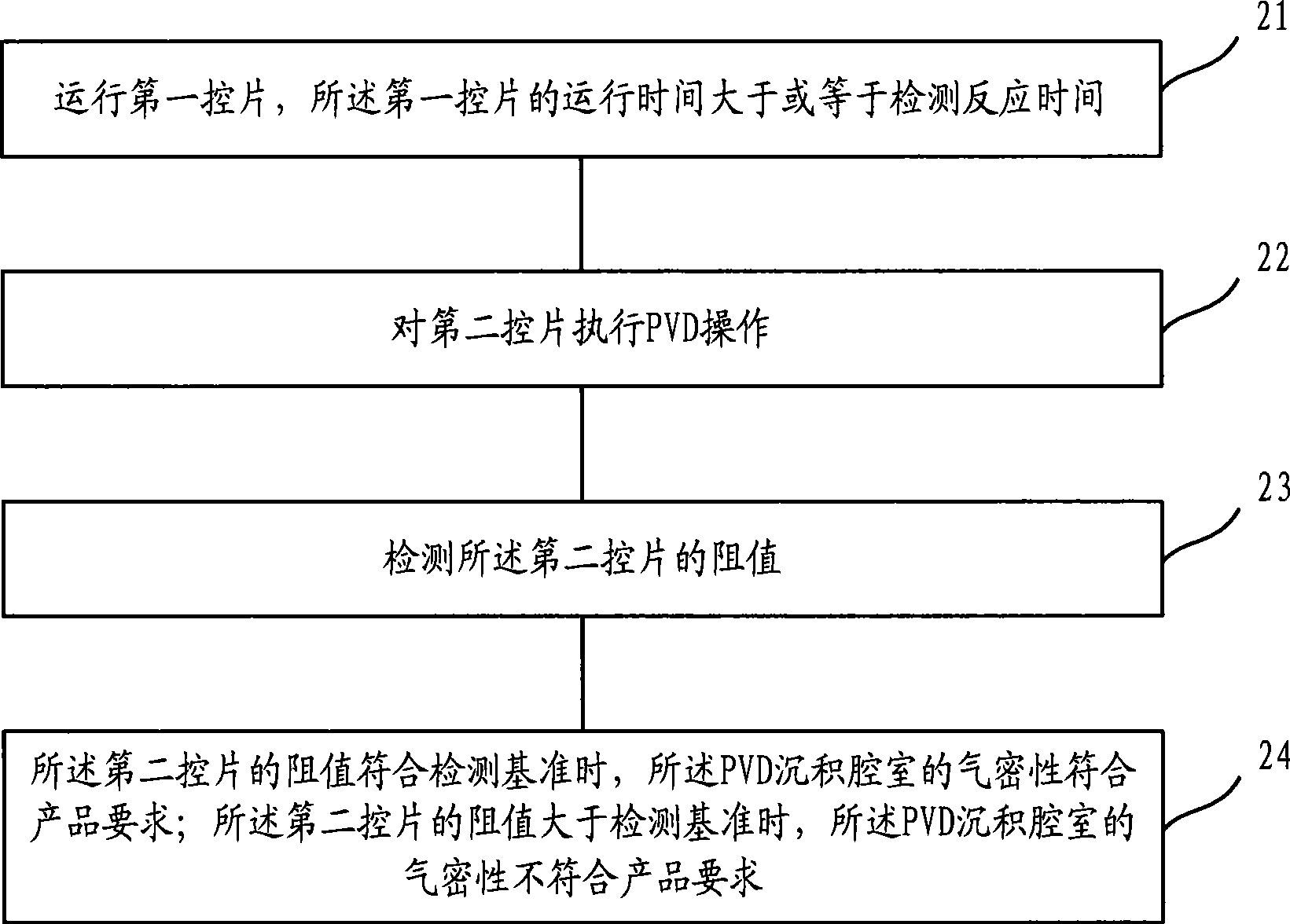
[0041] Such as figure 2 As shown, as the first embodiment of the present invention, the specific steps of applying the method provided by the present invention to detect the airtightness of the PVD deposition chamber include:
[0042] Step 21: Run the first control panel, the running time of the first control panel is greater than or equal to the detection reaction time.
Login to View More PUM
 Abstract
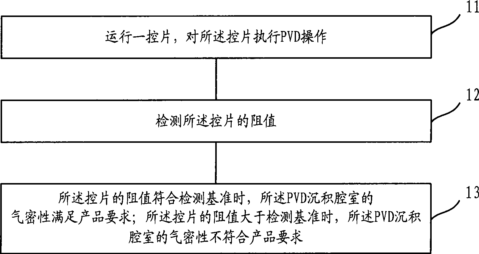
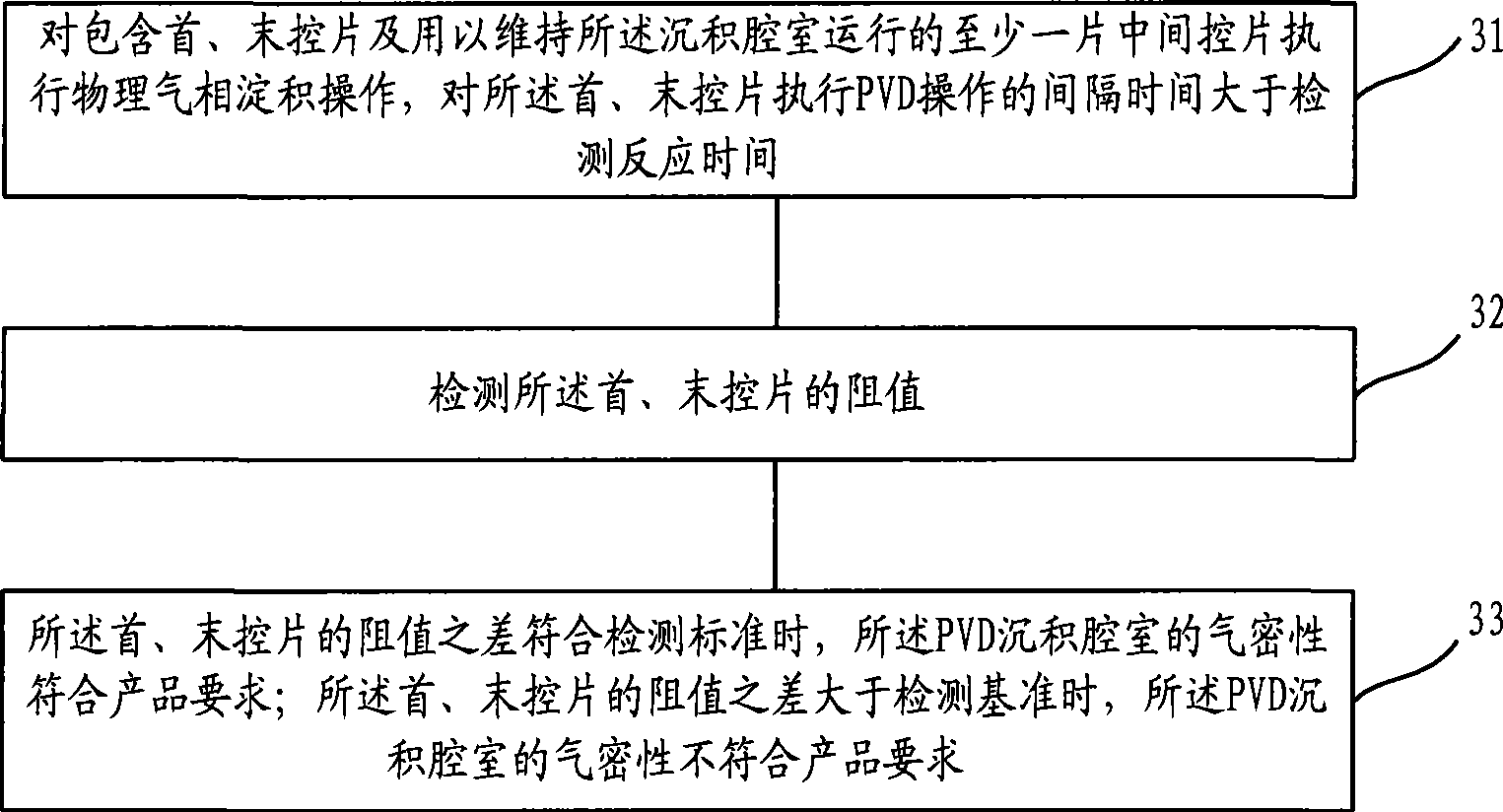
The invention relates to a method for detecting the air tightness of a physical vapor deposition and sedimentation cavity, which comprises the following steps: a first control wafer runs, and the running time of the first control wafer is more than or equal to detecting reaction time; physical vapor deposition is carried out on a second control wafer; the resistance value of the second control wafer is detected; when the resistance value of the second control wafer conforms to a detecting standard, the air tightness of the physical vapor deposition and sedimentation cavity meets product requirements; when the resistance value of the second control wafer is more than the detecting standard, the air tightness of the physical vapor deposition and sedimentation cavity does not meet the product requirements. The method can timely detect abnormal situations of the physical vapor deposition and sedimentation cavity after running, thus being good for shooting trouble, so as to reduce the quantity of production when the physical vapor deposition and sedimentation cavity is at abnormal state, while not changing the environment in the physical vapor deposition and sedimentation cavity.
Description
technical field [0001] The invention relates to the technical field of semiconductor manufacturing, in particular to a method for detecting air tightness of a physical vapor deposition deposition chamber. Background technique [0002] Currently, traditional metallization processes used in semiconductor manufacturing, including evaporation, sputtering, and electroplating, are all subsumed into physical vapor deposition (PVD). In order to maintain the purity of the deposited film, the vacuum in the PVD deposition chamber is an important parameter in the PVD process. When empty, the vacuum in the PVD deposition chamber is typically 10 -9 T; during operation, the vacuum in the PVD deposition chamber is typically 10 -2 T; however, usually when the PVD deposition chamber starts to operate or after a period of operation, such as 24 hours, the operation of the PVD deposition chamber needs to be detected. [0003] The air tightness test of the PVD deposition chamber is an importan...
Claims
Login to View More Application Information
Patent Timeline
 IPC IPC(8): G01M3/40G01M3/02
Inventor 聂佳相苏娜胡宇慧
Owner SEMICON MFG INT (SHANGHAI) CORP
Features
- R&D
- Intellectual Property
- Life Sciences
- Materials
- Tech Scout
- Unparalleled Data Quality
- Higher Quality Content
- 60% Fewer Hallucinations
Learn More Browse by: Latest US Patents, China's latest patents, Technical Efficacy Thesaurus, Application Domain, Technology Topic, Popular Technical Reports.
© 2025 PatSnap. All rights reserved.Legal|Privacy policy|Modern Slavery Act Transparency Statement|Sitemap|About US| Contact US: help@patsnap.com


