
Capacitance type sensor

A capacitive sensor and container technology, applied in the direction of material capacitance, using electric/magnetic devices to transmit sensing components, liquid level indicators for physical variable measurement, etc., can solve the problems of inconvenient manufacturing of sensor probe shapes, and achieve design methods Flexible, flexible and convenient to use, and simple in structure

Inactive Publication Date: 2009-06-17
张学亮
View PDF0 Cites 17 Cited by
  • Summary
  • Abstract
  • Description
  • Claims
  • Application Information

AI Technical Summary

Problems solved by technology

[0013] Existing capacitive sensors usually detect dielectric materials, and the shape of the sensor probe is inconvenient to manufacture

Method used


Image

  • Capacitance type sensor
  • Capacitance type sensor
  • Capacitance type sensor

Examples


Embodiment 1

[0055] The container of the present invention is an insulating container 3 . Such as Figure 5 Shown, the present invention is successfully used in medical transfusion alarm device, Image 6 yes Figure 5 The shown schematic diagram of the connection structure of the medical infusion alarm device applied to the infusion set.

Embodiment 2

[0057] The container of the present invention is a boiler. The invention is also successfully used in boiler water level control devices.

Embodiment 3

[0059] Specifically, the material of the insulating container 3 is glass or plastic.


PUM


Abstract

The invention discloses a capacitance type sensor, comprising capacitive polar plates and medium to be measured; wherein, the capacitance type sensor is arranged in a container, the capacitive polar plates form a probe unit and is fixed in the container, two capacitive polar plates of the probe unit are led to the outside of the container by two conductive films and are connected with a lead. By adopting the technical proposal, the size and shape of the probe unit formed by the two capacitive polar plates is designed flexibly, for instance, the measurement of liquid level can be achieved as long as the liquid to be measured is put into an insulated (glass and plastic for instance) container, while the probe unit of a sensor (namely the two capacitive polar plates) is closely adhered to the outside of the container by the two conductive films and the lead is elicited; or the probe unit can be made into a clamp-shaped device and is clamped in a corresponding position of the container when in use. The sensor of the invention is successfully applied to a medical transfusion warning device and a boiler water level control system. Compared with the existing non-contact sensor, the sensor in the invention has the advantages of simple structure and flexible and convenient use.

Description

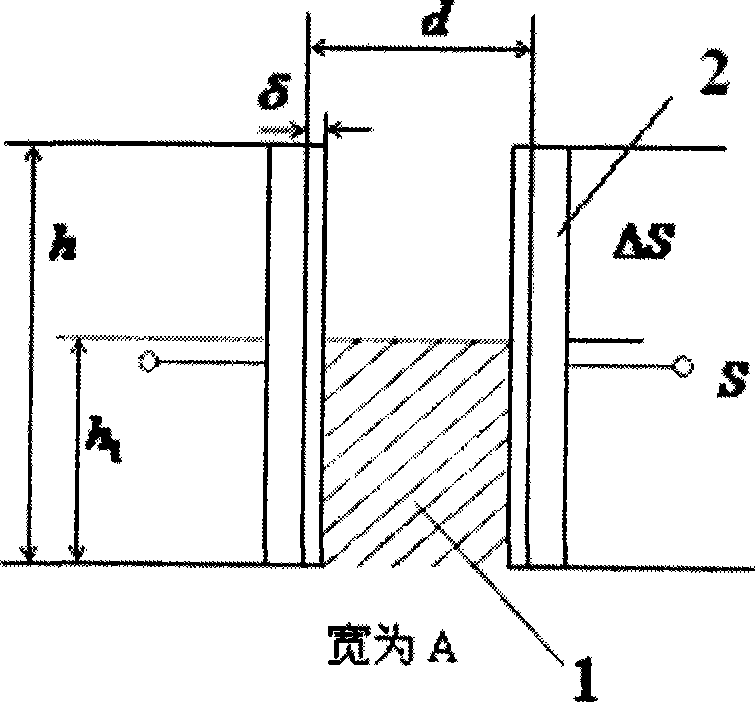
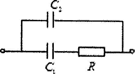
technical field [0001] The invention belongs to the technical field of measuring non-electrical quantity by electric measurement method, in particular, the invention relates to a capacitive sensor. Background technique [0002] There are various types of capacitive sensors, among which the variable medium sensor is closely related to the present invention, which can measure parameters such as temperature, humidity and medium thickness by measuring the parameters and dielectric constant of the medium. [0003] As shown in the accompanying drawings of this manual figure 1 as shown, [0004] C = ϵ 0 S d - δ + δ ϵ r [0005] in: [0006] ϵ ...

Claims


Application Information

Patent Timeline
Patent Type & Authority Applications(China)
IPC IPC(8): G01D5/24G01F23/26G01N27/22
Inventor 张学亮
Owner 张学亮
Learn More