Drive circuit and drive method for lcd device

A technology of liquid crystal display device and driving circuit, which is applied to static indicators, cathode ray tube indicators, instruments, etc., can solve problems such as flickering of liquid crystal display devices, and achieve the effect of reducing flickering

Inactive Publication Date: 2009-06-10
INNOCOM TECH SHENZHEN +1
View PDF0 Cites 26 Cited by
  • Summary
  • Abstract
  • Description
  • Claims
  • Application Information

AI Technical Summary

Problems solved by technology

[0012] In order to solve the flickering problem of the liquid crystal display device in the prior art, it is necessary to provide a driving circuit that can effectively solve the flickering problem of the liquid crystal display device
[0013] In addition, in order to solve the flickering problem of the liquid crystal display device in the prior art, it is also necessary to provide a driving method that can effectively solve the flickering problem of the liquid crystal display device

Method used


Image

  • Drive circuit and drive method for lcd device
  • Drive circuit and drive method for lcd device
  • Drive circuit and drive method for lcd device

Examples


Embodiment Construction

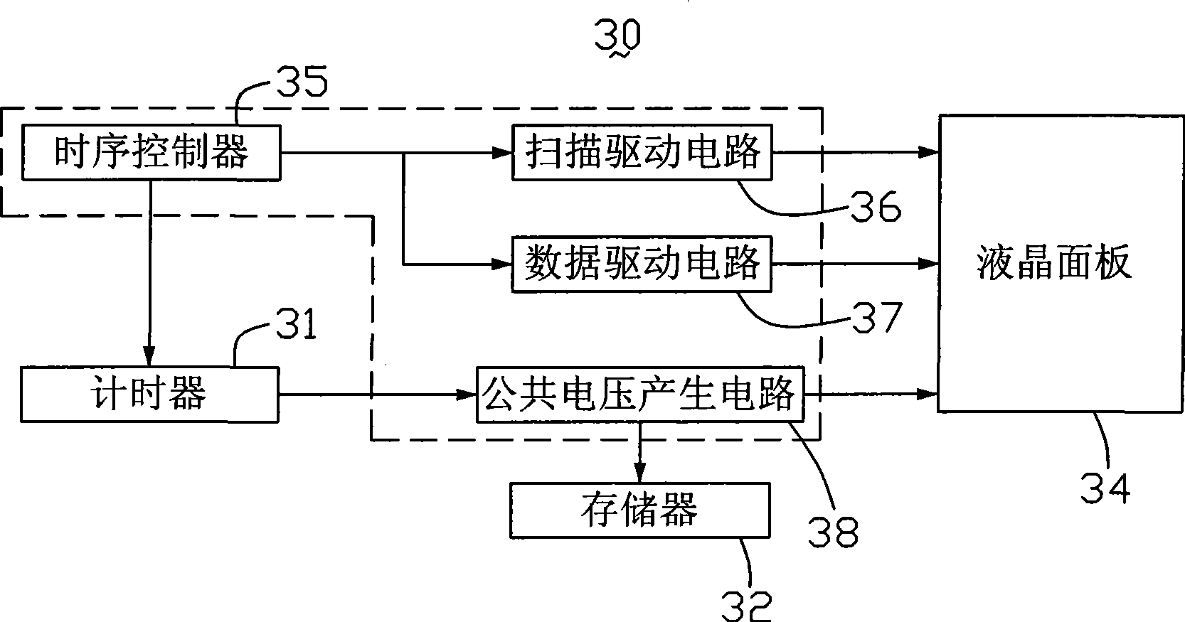
[0024] see image 3 , is a block diagram of the circuit structure of the first embodiment of the driving circuit of the liquid crystal display device of the present invention. The driving circuit 30 of the liquid crystal display device includes a timer 31, a memory 32, a liquid crystal panel 34 including a common electrode (not shown) and a plurality of pixel electrodes (not shown), a timing controller 35, a The scan driving circuit 36 ​​, a data driving circuit 37 and a common voltage generating circuit 38 . Wherein, there is a liquid crystal pinch between the common electrode and the pixel electrode of the liquid crystal panel 34, the timing controller 35, the scanning driving circuit 36, the data driving circuit 37 and the common voltage generating circuit 38 are used as the panel of the liquid crystal panel 34 The driving circuit provides driving voltage for the liquid crystal panel 34 to display images.

[0025] The timing controller 35 generates timing signals, which a...


PUM


Abstract

The invention relates to a drive circuit and a drive method for a liquid crystal display device. The drive circuit of the liquid crystal display device comprises a liquid crystal panel for displaying images, a panel drive circuit for driving the liquid crystal panel to work, a timer and a memory. The timer calculates the working time of the liquid crystal panel and outputs a time signal expressing the working time. The memory stores a lookup table which records time signals expressing the working time of the liquid crystal panel and optimal compensating voltage corresponding to each time signal. The optimal compensating voltage is voltage which compensates a liquid crystal voltage clamp between a pixel electrode and common voltage in the liquid crystal panel. The panel drive circuit receives the time signals output by the timer, looks up the optimal compensating voltage corresponding to the time signal from the lookup table, and applies the optimal compensating voltage on the liquid crystal panel. The drive circuit of the liquid crystal display device can effectively eliminate the flicker.

Description

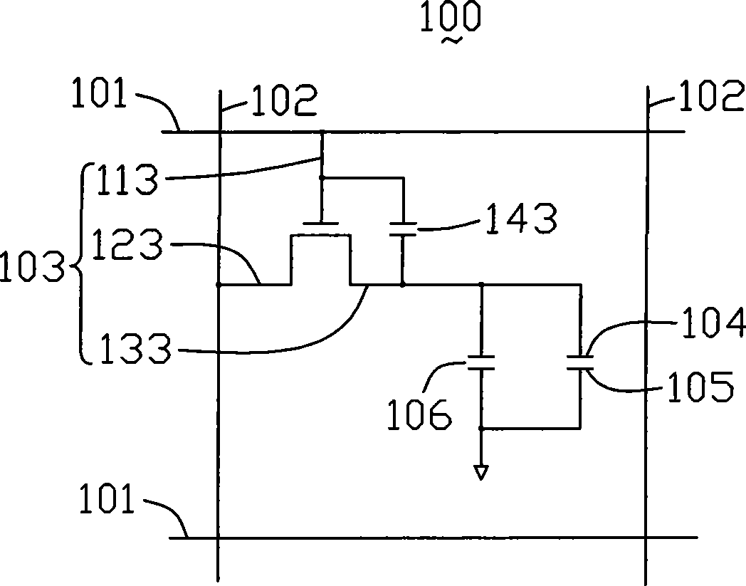
technical field [0001] The invention relates to a driving circuit and a driving method of a liquid crystal display device. Background technique [0002] Liquid crystal display devices have the advantages of lightness, thinness, shortness, and low power consumption, and have been widely used in modern information equipment such as notebook computers, mobile phones, and personal digital assistants. Generally, a liquid crystal display device is a dot-matrix display device, which includes a plurality of pixel units distributed in a matrix. [0003] see figure 1 , is an equivalent circuit diagram of a pixel unit in a liquid crystal display device. The pixel unit 100 is the smallest area defined by two adjacent gate lines 101 and two adjacent data lines 102, which includes a thin film transistor 103, a pixel electrode 104, a common electrode 105, a A liquid crystal layer (not shown) and a holding capacitor 106 are between the electrode 104 and the common electrode 105 . [000...

Claims


Application Information

Patent Timeline
Patent Type & Authority Applications(China)
IPC IPC(8): G09G3/36G09G5/36G02F1/133
Inventor 周伟冯沙
Owner INNOCOM TECH SHENZHEN
Why Eureka
Try Eureka