
Yarn leading roller apparatus for ring spinner

A ring spinning machine and yarn drawing technology, which is applied to spinning machines, continuous winding spinning machines, textiles and papermaking, etc., can solve the problem of non-parallelism of front roller pairs, large difference in pressure of each spindle, and increased pressure. Unstable pressure and other problems, to overcome changes in mechanical properties, improve uniformity, and reduce yarn defects

Inactive Publication Date: 2009-06-10
上海依福瑞实业有限公司
View PDF0 Cites 6 Cited by
  • Summary
  • Abstract
  • Description
  • Claims
  • Application Information

AI Technical Summary

Problems solved by technology

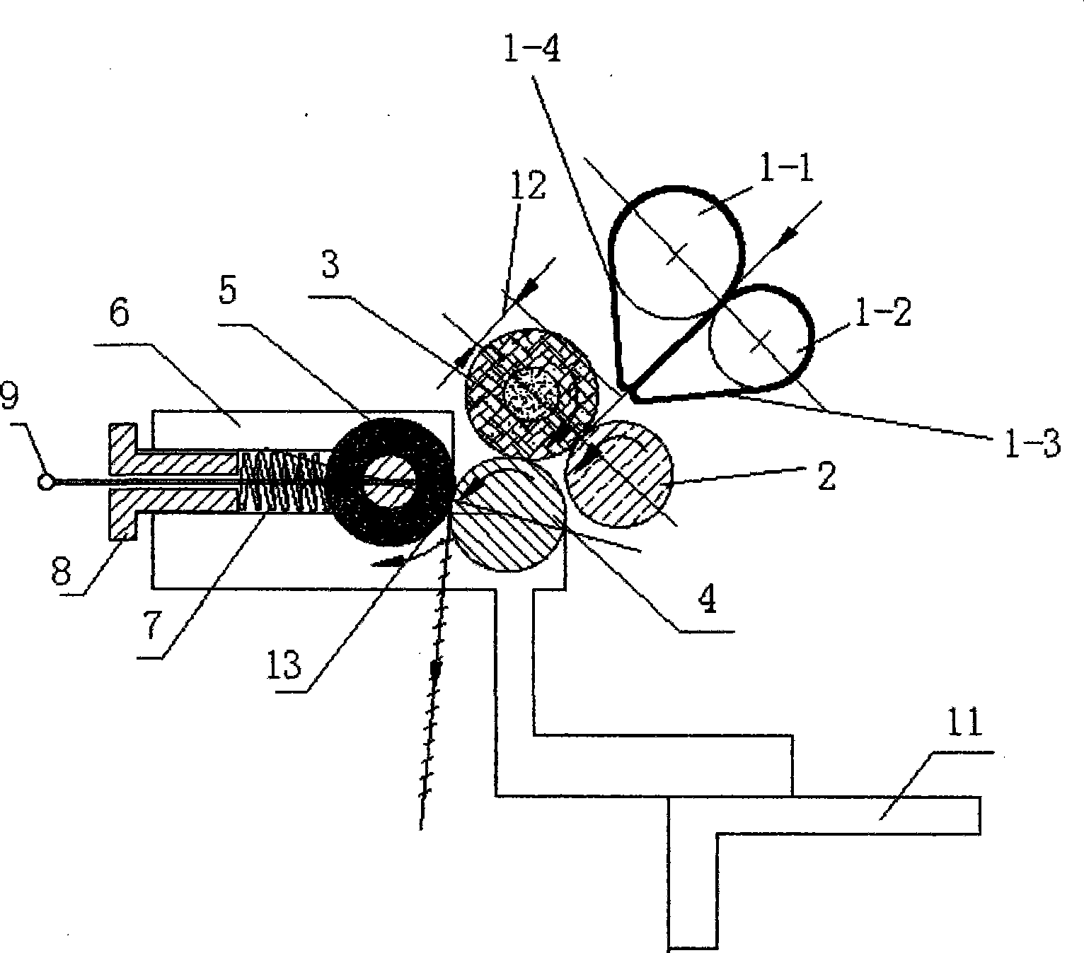
[0003] The purpose of this invention is to provide a yarn delivery roller device for ring spinning machines, that is, to install a yarn delivery roller device in the original cylindrical spring pressurized cradle to solve the problem of the front roller pair in the cylindrical spring pressurized cradle. Non-parallelism, unstable and uneven pressing pressure, conflicts in the adjustment of floating zone length and weak twist zone length, and big difference in the pressing pressure of each spindle on the same machine

Method used


Image

  • Yarn leading roller apparatus for ring spinner
  • Yarn leading roller apparatus for ring spinner
  • Yarn leading roller apparatus for ring spinner

Examples


Embodiment Construction

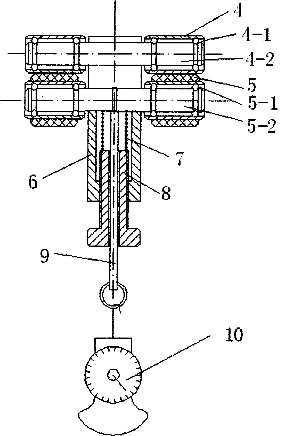
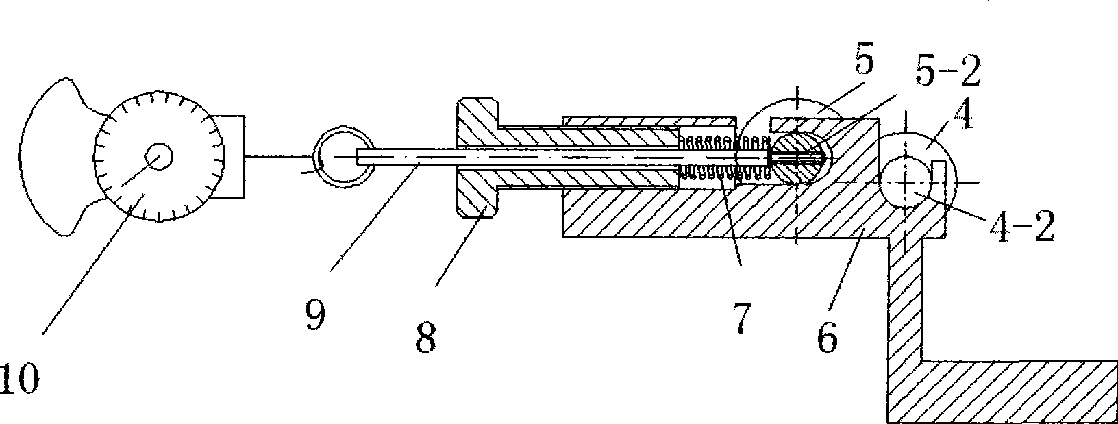
[0011] according to figure 1 As shown, yarn drawing roller 4 is respectively fixed on the two ends of roller mandrel 4-2 by bearing 4-1, and the center of roller mandrel 4-2 is fixed on the device seat 6. Yarn leading top roller 5 is connected on the two ends of yarn leading top roller mandrel 5-2 respectively by bearing 5-1, and the middle of yarn leading top roller mandrel 5-2 is installed in the chute of device seat 6 (see figure 2 ). The pressure spring 7 and the pressure screw 8 are installed in the hole of the device seat 6, and the two ends of the pressure spring 7 are respectively pressed against the middle of the yarn leading roller mandrel 5-2 and the pressure screw 8, and the pressure screw is rotated 8. The pressure between the yarn delivery roller 4 and the yarn delivery top roller 5 can be adjusted. Offer a hole in the middle of the pressure screw 8, a load cell 9 is adorned in the hole, and one end of the load cell 9 connects the yarn-leading top roller mandr...


PUM


Abstract

The invention discloses a doffing roller device for a ring spinner, in particular a doffing roller device for a cylindrical spring-pressurized rocking frame of the ring spinner. The doffing roller device consists of an original rocking frame, a doffing roller, a roller mandrel, a doffing belt roller, a doffing belt roller mandrel, a device seat, a pressurization spring, a pressurization bolt, a bearing, a force metering lever and a dynamometer. When used, a front belt roller of the original rocking frame drives the doffing roller to rotate; and the doffing roller drives the doffing belt roller to rotate. A drawing fiber strand passes through an original front roller pair, is transferred to between the doffing roller and the doffing belt roller and is twisted to form yarn. The doffing roller device has the advantages that yarn strips are even; the length of a floating region and a weak twisting region can be adjusted respectively and independently; and the pressurizing of the doffing belt roller can be directly measured and is convenient to implement.

Description

Technical field: [0001] The invention relates to a yarn delivery roller device for a ring spinning machine, in particular to a yarn delivery roller device for a cylinder spring pressurized cradle of the ring spinning machine. Background technique: [0002] The spring-loaded cradle of the ring spinning machine is the spun sliver required for drafting the roving sliver in the drafting of the ring spinning machine, so as to meet the quality requirements of the spun yarn. The cradle used in the existing ring spinning machine has three types: cylinder spring pressurization, air pressure pressurization and plate spring pressurization, among which the market share of the cylindrical spring pressurization form is 85%. Cylindrical spring-loaded cradle, generally composed of cradle body, fixed body, fixed shaft, shaft pin, handle, eccentric lock plate, pressure rod, pressure spring, three pairs of top rollers and rollers, front roller pair and middle roller Deputy and back roller vic...

Claims


Application Information

Patent Timeline
Patent Type & Authority Applications(China)
IPC IPC(8): D01H5/74D01H5/50D01H1/14
Inventor 许云生王睿
Owner 上海依福瑞实业有限公司
Learn More