Eureka AIR delivers breakthrough ideas for toughest innovation challenges, trusted by R&D personnel around the world.

Carbon fiber reinforcement resin base composite material lattice structural-component conforming die and method

A technology for reinforcing resin-based and composite materials, which is applied in the field of carbon fiber-reinforced resin-based composite material mesh structure forming molds and molding fields, which can solve the problems of high labor intensity, too high rib height, low fiber volume content, etc., to achieve The effect of low mold cost, low porosity and high density

Active Publication Date: 2011-09-21
AEROSPACE RES INST OF MATERIAL & PROCESSING TECH
View PDF0 Cites 0 Cited by
  • Summary
  • Abstract
  • Description
  • Claims
  • Application Information

AI Technical Summary

Problems solved by technology

The disadvantage is that the fiber volume content is low, the height of the ribs cannot be too high, and the labor intensity is high.

Method used


Image

  • Carbon fiber reinforcement resin base composite material lattice structural-component conforming die and method
  • Carbon fiber reinforcement resin base composite material lattice structural-component conforming die and method
  • Carbon fiber reinforcement resin base composite material lattice structural-component conforming die and method

Examples


Embodiment 1

[0055] Such as figure 1 As shown, the carbon fiber-reinforced resin-based composite material grid structural member forming mold according to the present invention, it is the main mold 1, the split grid male mold 2, and the female mold 8 from the inner layer to the outer layer; two end frames Pressure ring 6 is respectively arranged on the top and the bottom of main body mold 1 and split grid male mold 2 combination; described main body mold 1 is made of steel; described split grid male mold 2, female mold 8 are all Made of aluminum alloy. Such as image 3 As shown in Fig. 4, the split grid male mold 2 is divided into several petals in the longitudinal direction and the circumferential direction.

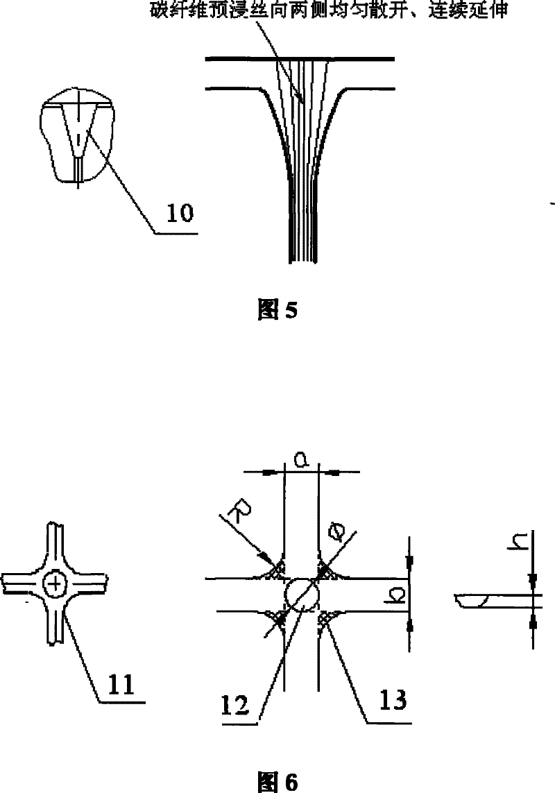
[0056] Such as Figure 5 As shown, the split grid male mold 2 is provided with expansion grooves 10 at both ends of the longitudinal grid ribs.

[0057] As shown in Figure 6, the split grid male mold 2 draws a dimple 12 at the center of the grid node 11, and is provided with cha...

Embodiment 2

[0081] Such as Figure 7 As shown, the carbon fiber-reinforced resin-based composite material grid structural member forming mold has the main mold 1, the silicone rubber grid male mold 9, and the female mold 8 in sequence from the inner layer to the outer layer; the two end frame pressure rings 6 are respectively set Above and below the combination of the main body mold 1 and the silicone rubber grid male mold 9; the main body mold 1 is made of steel; the silicone rubber grid mold is made of silicone rubber material; Die 8 is made of aluminum alloy.

[0082] The silicone rubber grid male mold 9 is provided with expansion grooves at both ends of the longitudinal grid reinforcement ribs. The silicone rubber grid male mold 9 is provided with chamfers at the four corners of the grid nodes; the radius R of the chamfers is calculated by the following formula:

[0083] R ≈ a × b ...


PUM

PropertyMeasurementUnit
depthaaaaaaaaaa

Abstract

The invention relates to a mould and a method for molding a carbon fiber reinforced resin-based composite material grid structural piece. The mould for molding the carbon fiber reinforced resin-based composite material grid structural piece consists of a main body mould, a splitting grid male mould and a splitting grid female mould sequentially from an inner layer to an outer layer; and two end frame pressure loops are arranged on the upper part and the lower part of the main body mould and the splitting grid male mould respectively. The mould can be repeatedly used for a plurality of times; a grid reinforced rib of a molded product has higher dimension precision and position precision; and the quality of the product has good consistency. The method for molding the carbon fiber reinforcedresin-based composite material grid structural piece is wholly co-cured and molded, is favorable for ensuring the consistency of the whole performance and quality of the composite material grid structural product so that the structure has good rigidity and bearing capacity.

Description

technical field [0001] The invention relates to a molding die and a molding method for a composite material grid structure part, in particular to a molding die and a molding method for a carbon fiber-reinforced resin-based composite material grid structure part. Background technique [0002] With the development of the aerospace industry, especially the continuous improvement of the technological level of aerospace materials, the grid structure of composite materials has been more and more widely used. The grid structure made of unidirectional composite materials can give full play to the advantages of composite materials. The continuous improvement of design and manufacturing process is expected to reduce the manufacturing cost as soon as possible, and has broad development prospects and great potential. The most common mold methods for forming grids are mainly the following three: one is soft molding, which is a leading technology of the USAF Phillips Laboratory and is use...

Claims


Application Information

Patent Timeline
Patent Type & Authority Patents(China)
IPC IPC(8): B29C70/54B29C33/42B29C33/38B29C70/34B29K307/04
Inventor 党旭佞李煊蒋元兴孙宏杰
Owner AEROSPACE RES INST OF MATERIAL & PROCESSING TECH
Why Eureka
Eureka Blog
Learn More