Detachable concrete test block mold with convenient demolding function

A technology for concrete test blocks and molds, applied in molds, manufacturing tools, ceramic molding machines, etc., can solve problems such as reduced work efficiency, difficulty in demoulding, and damage to the mold itself, so as to solve difficulties in demoulding, avoid damage, and save storage effect of space

Pending Publication Date: 2018-04-13
JILIN UNIV
View PDF0 Cites 4 Cited by
  • Summary
  • Abstract
  • Description
  • Claims
  • Application Information

AI Technical Summary

Problems solved by technology

[0002] In civil engineering experiments, standard concrete test blocks are often used to test the strength of concrete, and the formation of test blocks requires concrete test block molds. At present, the most used molds are formed by consolidating a bottom plate and four vertical plates into a whole. The concrete test block is formed at one time. Due to the friction between the vertical plate surface and the side of the concrete test block, and the mold cannot be disassembled as a whole, it is difficult to remove the film after the test block is formed. Usually, it is used The concrete test block can be taken out by beating the mold, but this method is easy to cause damage to the test block and the mold itself, and also reduces work efficiency

Method used


Image

  • Detachable concrete test block mold with convenient demolding function
  • Detachable concrete test block mold with convenient demolding function
  • Detachable concrete test block mold with convenient demolding function

Examples


Embodiment Construction

[0022] The present invention is described in detail below in conjunction with accompanying drawing:

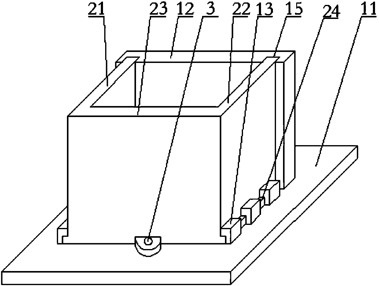
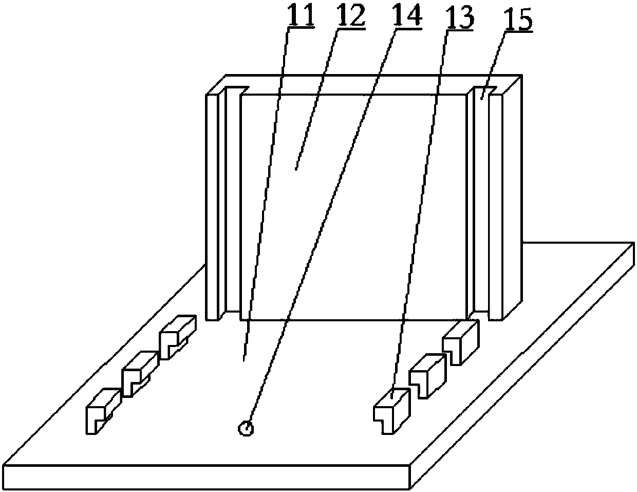
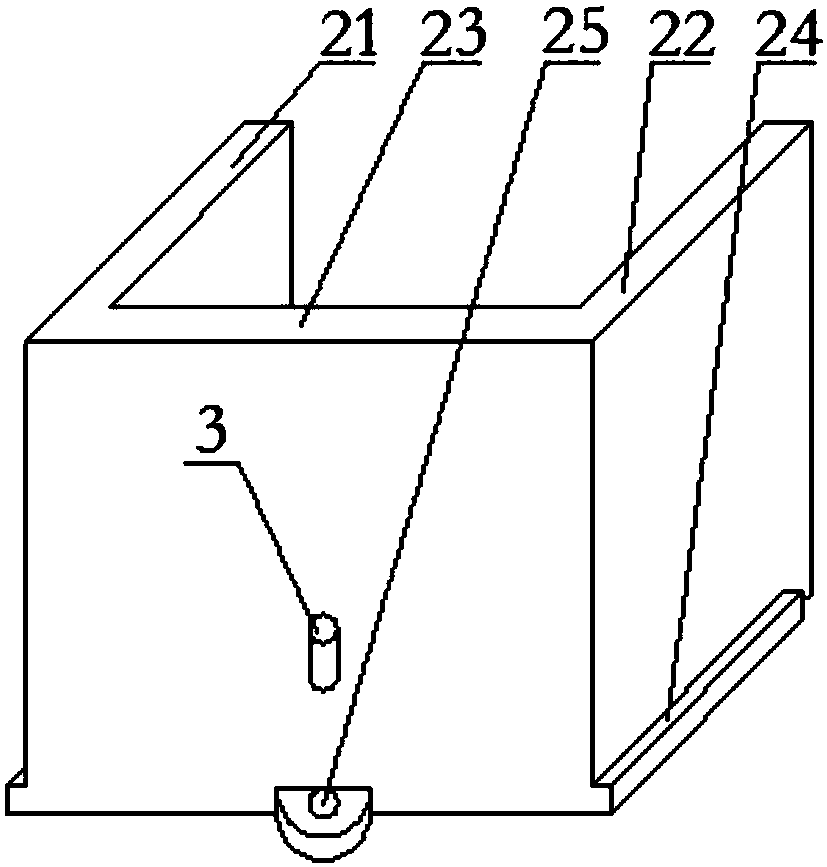
[0023] refer to figure 1 , a detachable concrete test block mould, which is convenient for demoulding, mainly consists of a base plate 11, a rear formwork 12, a left formwork 21, a right formwork 22, a front formwork 23 and pins 3. refer to figure 2 , the base plate 11 and the rear formwork 12 are poured and connected as a whole, the base plate 11 is provided with a limit hole A14 and a limit card groove 13, and the rear formwork 12 is provided with a limit groove 15; refer to image 3 , the left and right side templates and the front template 23 are poured and connected as a whole, the middle position of the front template 23 bottoms is also provided with a limiting hole B25, and the left and right template bottoms are all provided with a limiting clip 24.

[0024] Before pouring the test block, the mold is assembled first. The assembly process is as follows: first, align ...


PUM


Abstract

The invention belongs to the technical field of concrete construction and discloses a detachable concrete test block mold with a convenient demolding function. The detachable concrete test block moldmainly comprises a baseplate, a rear mold plate, a left mold plate, a right mold plate, a front mold plate and a pin, wherein the baseplate and the rear mold plate are connected into a whole; a limiting hole A and limiting clamping grooves are formed in the baseplate; limiting grooves are formed in the rear mold plate; the left mold plate, the right mold plate and the front mold plate are connected into a whole; a limiting hole B is formed in the middle position of the bottom of the front mold plate; limiting clamping strips are arranged at the bottoms of both the left mold plate and the rightmold plate, and can be completely embedded in the limiting clamping grooves; the free ends of the left mold plate and the right mold plate can be completely embedded in the limiting grooves of the rear mold plate; and the pin is inserted into the limiting hole A of the baseplate and the limiting hole B of the front mold plate. By adoption of the detachable concrete test block mold disclosed by the invention, the problem that a test block is difficult to demold can be solved, and the test block and the detachable concrete test block mold can be protected against damage during the demolding process. Due to the detachable effect of the detachable concrete test block mold, the detachable concrete test block mold can be detached for placement when not in use, and then the storage space can besaved.

Description

technical field [0001] The invention belongs to the technical field of concrete construction, and relates to a mold for forming concrete test blocks in civil engineering experiments, in particular to a detachable concrete test block mold which is convenient for demoulding. Background technique [0002] In civil engineering experiments, standard concrete test blocks are often used to test the strength of concrete, and the formation of test blocks requires concrete test block molds. At present, the most used molds are formed by consolidating a bottom plate and four vertical plates into a whole. The concrete test block is formed at one time. Due to the friction between the vertical plate surface and the side of the concrete test block, and the mold cannot be disassembled as a whole, it is difficult to remove the film after the test block is formed. The concrete test block is taken out by beating the mold, but this method is easy to cause damage to the test block and the mold it...

Claims


Application Information

Patent Timeline
IPC IPC(8): B28B7/00
CPCB28B7/0094
Inventor 王庆华王建新关力维武京李贝娜冮传鹏
Owner JILIN UNIV
Why Eureka
Try Eureka