


Quick Research
Generate reliable direction feasibility study reports for your R&D in just a few steps.

Technical Q&A
Discover and master advanced knowledge NOW. Basics, ideas, possibilities, all at once.

Find Solutions
As an expert in R&D theories, this can generate solutions to your technical problems instantly.

Evaluate Feasibility
Analyze your overall solution with one click, know your potential R&D risks in advance.

Monitor Landscape
Get weekly tech updates, stay abreast of the latest tech innovations and key insights.
Exoskeleton finger with fingertip location following and fingertip bidirectional force feedback function
An exoskeleton and force feedback technology, applied in manipulators, manufacturing tools, mechanical control devices, etc., can solve problems such as bloated structure, inability to distinguish between "contact" and "non-contact" modes, and strong friction.
- Summary
- Abstract
- Description
- Claims
- Application Information
AI Technical Summary
Problems solved by technology
Method used
Image


Examples
specific Embodiment approach 1
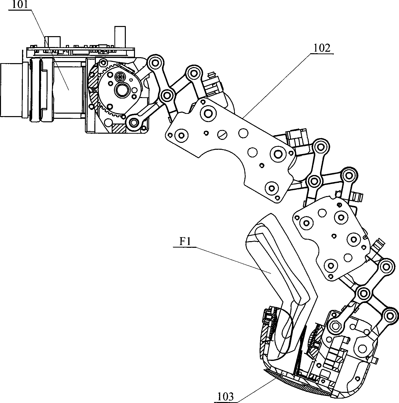
[0005] Specific implementation mode one: (see figure 1 with figure 2 ) This embodiment is composed of a motor drive system 101, an extensible exoskeleton mechanism 102 and fingertips 103, the output end of the motor drive system 101 is connected with the input end of the extensible exoskeleton mechanism 102, and the extensible exoskeleton The output end of the mechanism 102 is connected with the fingertip 103 .
specific Embodiment approach 2
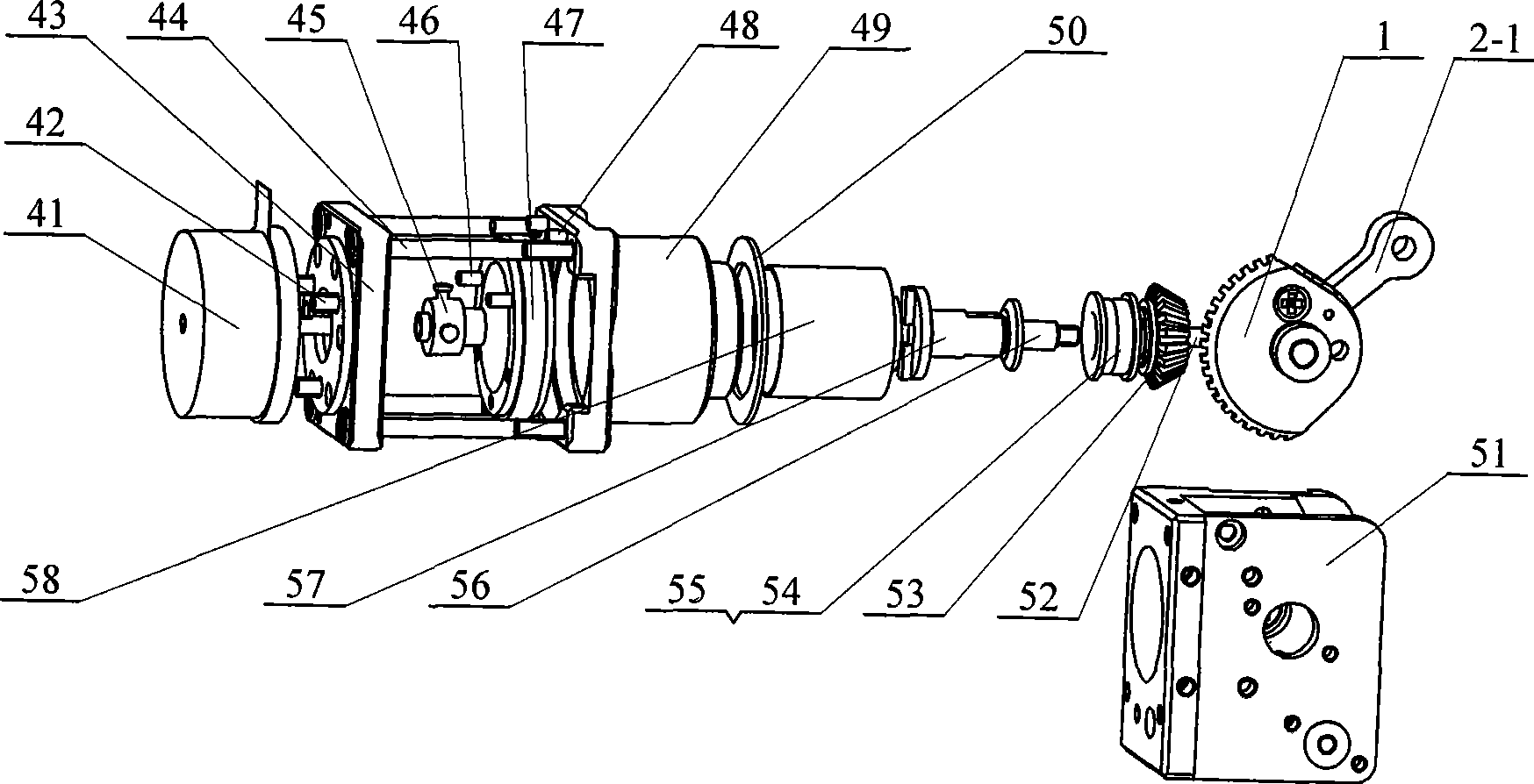
[0006] Specific implementation mode two: (see Figure 1 ~ Figure 3 ) The motor driving mechanism 101 described in this embodiment is composed of a DC brushless motor 41, a motor fixing screw 42, a motor base 43, a motor base mounting screw 44, a motor output coupling 45, a motor base positioning pin 46, and a mounting pad cover 47 , gear box mounting screw 48, gear box mounting base 49, gasket 50, first frame 51, bevel gear fixing screw 52, output bevel gear 53, inner sleeve 54, outer sleeve 55, sleeve fixing screw 56 , the output coupling 57 of the harmonic reducer and the harmonic reducer 58, the DC brushless motor 41 is fixed on the motor base 43 through the motor fixing screw 42, and the motor is connected between the reducer installation base 49 and the motor base 43 Seat installation screw 44, the edge place of reduction box installation base 49 rear ends is provided with reduction box installation screw 48, the rear portion of reduction box installation base 49 is pro...
specific Embodiment approach 3
[0007] Specific implementation mode three: (see figure 1 , figure 2 , Figure 4 with Figure 7 ) The extensible exoskeleton mechanism 102 of this embodiment consists of an input bevel gear 1, a second frame 81, a third frame 82, two first connecting plates 18, two second connecting plates 21, and a fingertip interface 15 , the first parallelogram linkage mechanism 2, the second parallelogram linkage mechanism 8, the third parallelogram linkage mechanism 14, the first wire rope transmission mechanism 5 and the second wire rope transmission mechanism 11, two first connecting plates 18 They are respectively arranged on both sides of the third frame 82, and the two second connecting plates 21 are respectively arranged on both sides of the second frame 81. The first parallelogram linkage mechanism 2 is composed of the first connecting rod 2- 1. The second connecting rod 2-2, the third connecting rod 2-3 and the fourth connecting rod 2-4 are composed, and the second parallelogra...
PUM
 Abstract
Description
Claims
Application Information
 - R&D Engineer
- R&D Manager
- IP Professional
- Industry Leading Data Capabilities
- Powerful AI technology
- Patent DNA Extraction
Browse by: Latest US Patents, China's latest patents, Technical Efficacy Thesaurus, Application Domain, Technology Topic, Popular Technical Reports.
© 2024 PatSnap. All rights reserved.Legal|Privacy policy|Modern Slavery Act Transparency Statement|Sitemap|About US| Contact US: help@patsnap.com