
Pulverized coal burner

A pulverized coal burner and pulverized coal technology, applied in the direction of burners, burners burning powder fuel, combustion types, etc., can solve the problems of no application of micro-oil combustion technology, difficulties in ignition and stable combustion, and abnormal special structure of the burner, etc. question

Active Publication Date: 2009-06-03
EASTERN BOILER CONTROL CO LTD +1
View PDF0 Cites 9 Cited by
  • Summary
  • Abstract
  • Description
  • Claims
  • Application Information

AI Technical Summary

Problems solved by technology

At present, the four-corner tangential circle arrangement of other conventional power station pulverized coal boilers and the micro-oil combustion system of the wall-arranged burners have become popular. However, due to the poor quality of coal used in W-type flame boilers, the burner structure is unusually special. Ignition and stable combustion are particularly difficult, and there is no precedent for the application of micro-oil combustion technology

Method used


Image

  • Pulverized coal burner
  • Pulverized coal burner
  • Pulverized coal burner

Examples


Embodiment 1

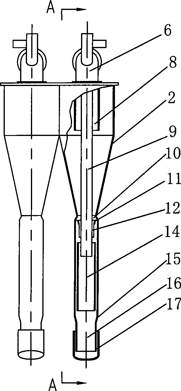
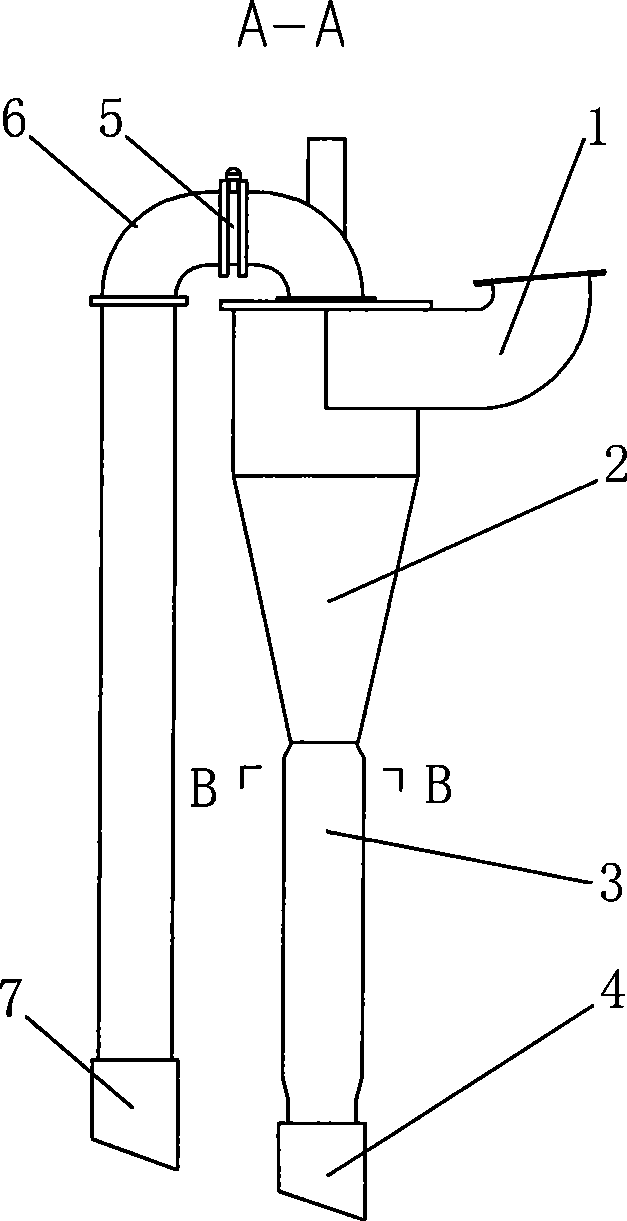
[0022] Example 1, such as figure 1 , 2 , Shown in 3, a kind of pulverized coal burner comprises two and has the cyclone tube 2 of primary air powder tangential inlet, and the cyclone tube is two parallel cylinders. The middle part of the cyclone 2 is a tapered constriction section; the exhaust gas pipeline 6 inserted from the top of the cyclone 2 and having the exhaust air regulating damper 5 is arranged in the primary pulverized coal combustion chamber 14 in the straight section 3 of the outlet of the cyclone 2 And secondary pulverized coal combustion chamber 16. It also includes a micro-oil gasification oil gun 9. The micro-oil gasification oil gun 9 is inserted from the top of the cyclone 2 and passes through the inlet 8 of the exhaust gas pipeline to the inlet of the first-stage pulverized coal combustion chamber 14. A more retracted throat 10 is provided at the junction of the constricted section of the cyclone 2 and the straight section 3 .

Embodiment 2

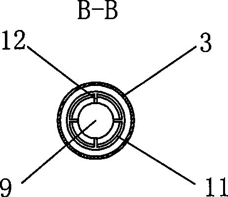
[0023] Embodiment 2, a pulverized coal burner, in order to further concentrate the pulverized coal concentrated at the throat, a concentration ring 11 is provided outside the throat 10 . All the other are with embodiment 1.

Embodiment 3

[0024] Embodiment 3, a pulverized coal burner, in order to eliminate the primary pulverized coal cyclone coming out of the cyclone and make the burner burn better, a derotation vane 12 is provided outside the throat 10 . All the other are with embodiment 1.


PUM


Abstract

A pulverized coal burner comprises at least one cyclone with a primary air powder tangential inlet line and a middle tapered shrinkage segment; an exhaust gas pipe having an exhaust gas adjusting air door and inserted on the top of the cyclone; a primary pulverized coal burning chamber and a secondary pulverized coal burning chamber arranged on the straight outlet segment of the cyclone; a micro-oil oil gun arranged on the top of the cyclone and inserted and penetrating the inlet of the exhaust gas pipe to the inlet of the primary pulverized coal burning chamber; a concentration ring and a rotation-eliminating blade arranged outside the throat at the interface of the shrinkage segment and the straight outlet segment of the cyclone; and a secondary air nozzle arranged at the outlet of the secondary pulverized coal burning chamber. The pulverized coal burner can achieve burn a great amount of pulverized coal by strengthened combustion and gradual amplification of trace oil by adopting the technical measures, such as ignition using micro-oil gasification oil gun, secondary pulverized coal burning, adjustable exhaust gas flow rate and pulverized coal concentration ratio, further pulverized coal concentration and rotation elimination, thereby achieving ignition of anthracite and lean coal, and achieving high oil saving rate. The coal burner is particularly suitable for W-shaped flame boiler.

Description

technical field [0001] The invention relates to a pulverized coal burner, in particular to a burner for a W-shaped flame boiler burning anthracite or lean coal, and belongs to the technical field of combustion technology and equipment. Background technique [0002] my country is one of the few countries in the world where coal is the main primary energy source. Since the ignition and combustion of coal is much more difficult than that of oil and gas, a large amount of fuel oil or gas is generally used for ignition and stable combustion under the conditions of boiler start-up and low-load operation. Although China's coal reserves are relatively abundant, the quality of coal varies greatly. In most parts of southern China, as well as parts of northern China, there are a large number of low-quality coal resources, especially anthracite and lean coal with high ash content and low volatile content. W-type flame boiler is currently one of the best technologies for anthracite and...

Claims


Application Information

Patent Timeline
IPC IPC(8): F23D1/00
Inventor 周昊马德龙金黄蒲学森
Owner EASTERN BOILER CONTROL CO LTD
Learn More