
Hydraulic controlled vehicle power transmission mechanism

A technology of power transmission mechanism and transmission mechanism, applied in the direction of control devices, vehicle parts, transportation and packaging, etc., can solve the problems of troublesome design of cabin parts, difficulty of large layout, complex control mechanism and corresponding pipeline layout, etc., to achieve Save space, improve reliability, and improve transmission efficiency

Inactive Publication Date: 2009-06-03
SAIC-GM-WULING AUTOMOBILE CO LTD
View PDF0 Cites 0 Cited by
  • Summary
  • Abstract
  • Description
  • Claims
  • Application Information

AI Technical Summary

Problems solved by technology

[0002] In the traditional front-rear drive engine compartment, the layout of various control mechanisms and corresponding pipelines is very complicated, which is the most difficult problem to solve in the process of vehicle design and manufacturing
For the requirements of the space clearance in the engine compartment, the influence of many aspects needs to be considered, which in turn brings great trouble to the design of the components in the compartment
[0003] Existing clutch controllers mostly adopt the form of cables. Due to the flexibility of the cables, their distribution requires a certain space, and their direction makes the layout more difficult.

Method used


Image

  • Hydraulic controlled vehicle power transmission mechanism
  • Hydraulic controlled vehicle power transmission mechanism
  • Hydraulic controlled vehicle power transmission mechanism

Examples


Embodiment Construction

[0016] The present invention will be further described below in conjunction with the description of the drawings and specific embodiments.

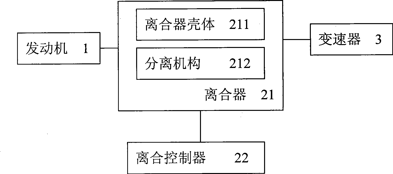
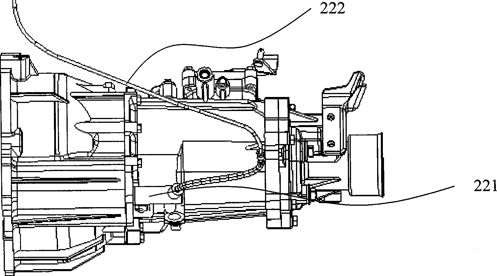
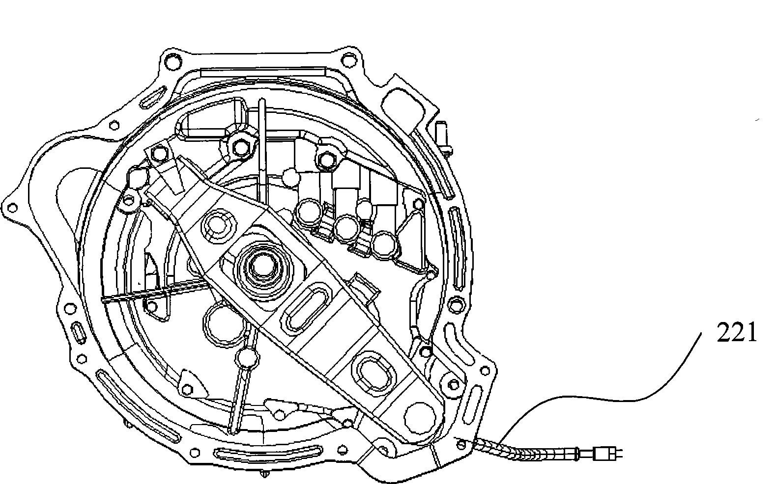
[0017] Such as figure 1 with image 3 As shown, a hydraulically controlled vehicle power transmission mechanism includes an engine 1, a transmission 3 and a clutch 21 arranged between the engine 1 and the transmission 3, and the clutch 21 is connected to a clutch controller 22; the clutch control The device 22 is a hydraulic control actuator, which includes a hydraulic master cylinder 221 and an oil pipe 222 communicating with the internal oil circuit of the master cylinder 221; the hydraulic master cylinder 221 is arranged horizontally. On a vehicle, generally the plane on which the vehicle is located is horizontal. At this time, the axis direction of the clutch 21 and the axis center direction of the master cylinder are both horizontal, and their directions are consistent.

[0018] The oil pipes 222 are freely distributed in the engin...


PUM


Abstract

The invention provides a hydraulic controlled vehicle power transmission mechanism, comprising: an engine, a transmission and a clutch arranged between the engine and the transmission. The clutch is connected with a clutch controller; the clutch controller is a hydraulic controlled implementing mechanism, comprising a hydraulic main cylinder and pipelines connecting oil-paths in the main cylinder; the main cylinder is horizontally set, axial direction being identical to axial line of the clutch. Beneficial effect of the invention is that the hydraulic clutch controller is used and the hydraulic main cylinder is horizontally set, which improves reliability of the hydraulic clutch controller and saves space in the engine area. In addition, a push type shift fork separation mechanism is used to improve transmission efficiency of the power transmission mechanism; mounting way of flange face seals dust greatly.

Description

【Technical field】 [0001] The invention relates to the field of vehicle manufacturing, in particular to a hydraulically controlled vehicle power transmission mechanism. 【Background technique】 [0002] In the traditional front-rear drive engine compartment, the layout of various control mechanisms and corresponding pipelines is very complicated, which is the most difficult problem to solve in the process of vehicle design and manufacturing. For the requirements of the space gap in the engine compartment, the influence of many aspects needs to be considered, which brings a lot of trouble to the design of the components in the compartment. [0003] The existing clutch controllers mostly adopt the form of cables. Due to the softness of the cables, their distribution requires a certain space, and their directions make the layout more difficult. 【Content of invention】 [0004] In order to solve the existing technical problems, the present invention provides a hydraulically contr...

Claims


Application Information

Patent Timeline
Patent Type & Authority Applications(China)
IPC IPC(8): B60K23/02B60K17/02
Inventor 黎谦覃高鹏崔硕方兵
Owner SAIC-GM-WULING AUTOMOBILE CO LTD
Learn More