


Quick Research
Generate reliable direction feasibility study reports for your R&D in just a few steps.

Technical Q&A
Discover and master advanced knowledge NOW. Basics, ideas, possibilities, all at once.

Find Solutions
As an expert in R&D theories, this can generate solutions to your technical problems instantly.

Evaluate Feasibility
Analyze your overall solution with one click, know your potential R&D risks in advance.

Monitor Landscape
Get weekly tech updates, stay abreast of the latest tech innovations and key insights.
Elevator control system
A technology of elevator control and elevator car, which is applied in elevators, transportation and packaging, and can solve the problems of increased capacity, complicated reading methods, and large time-consuming
- Summary
- Abstract
- Description
- Claims
- Application Information
AI Technical Summary
Problems solved by technology
Method used
Image

Examples
Embodiment 1
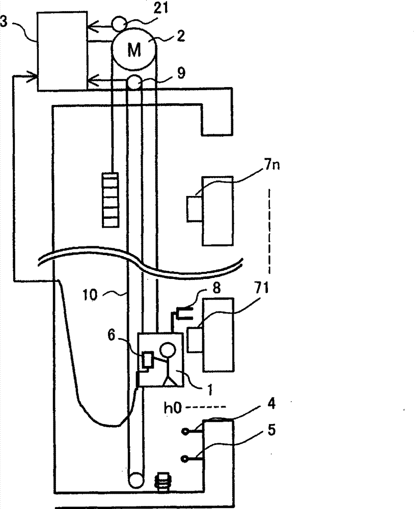
[0035] figure 1 It is a schematic diagram of the control system of the elevator in the first embodiment of the present invention. As shown in the drawing, a hoist 2 including a drive motor for raising and lowering the elevator car 1, and a control device 3 for controlling the drive of the hoist 2 are provided. Normally, the speed control of the drive motor is performed by comparing the speed command of the elevator with the output of the rotary encoder 21 for detecting the rotational speed of the hoist 2 .
[0036] As a safety device of the elevator terminal floor, a limit switch 4 outputting a stop command for limiting the descent of the elevator car 1 and a final limit switch 5 arranged below the limit switch 4 are provided.
[0037] For maintenance operation, a connector is provided inside the elevator car 1, to which the controller 6 can be connected and also detached. When performing maintenance operation, after the maintenance personnel connect the controller 6 to the...
Embodiment 2
[0054] Figure 7 is a processing flowchart of the second embodiment of the present invention. The focus of the second embodiment is the final limit switch 5 . Usually, the final limit switch 5 is a safety device provided in order to deal with the situation that the elevator car greatly exceeds the parking position due to a major failure during normal operation. Therefore, when the final limit switch 5 is set to act on it, the power supply to the main circuit of the power conversion device is cut off to stop the power supply to the winch, and it is forbidden to restart and reset in an automatic operation mode.
[0055] The second embodiment is when the elevator with high lift descends and stops towards the bottom floor during maintenance operation, although the first embodiment is adopted, unfortunately it is still a safety measure when the final limit switch 5 is actuated.
[0056] First, in step 71, when the operation of the final limit switch 5 is detected, in step 72, the...
Embodiment 3
[0059] Figure 8 is a processing flowchart of the third embodiment of the present invention. The focus of the third embodiment is story height measurement. The floor height measurement is an operation performed to store the elevation value of each floor from the standard floor in the built-in storage device of the control device 3 .
[0060] For example, if figure 1 As shown, the elevator car 1 is raised from the standard floor (for example, the bottom limit switch), and the position detector 8 detects the number of pulses when passing through the shielding plates 71-7n, thereby grasping the parking position of each floor. In this way, the floor height values of the shielding panels 71 - 7n of all floors up to the highest floor are stored. Usually, floor height measurement is performed at the time of commissioning before building completion, and the operation of the elevator car 1 at this time is performed at a low speed as in the low-speed operation of the first embodim...
PUM
 Abstract
Description
Claims
Application Information
 - R&D Engineer
- R&D Manager
- IP Professional
- Industry Leading Data Capabilities
- Powerful AI technology
- Patent DNA Extraction
Browse by: Latest US Patents, China's latest patents, Technical Efficacy Thesaurus, Application Domain, Technology Topic, Popular Technical Reports.
© 2024 PatSnap. All rights reserved.Legal|Privacy policy|Modern Slavery Act Transparency Statement|Sitemap|About US| Contact US: help@patsnap.com