Winding device and winding method

A technology of winding device and winding method, which is applied in the direction of electromechanical devices, electrical components, manufacturing motor generators, etc., to achieve the effect of real stop

Inactive Publication Date: 2016-07-06
NIDEC MACHINERY
View PDF7 Cites 0 Cited by
  • Summary
  • Abstract
  • Description
  • Claims
  • Application Information

AI Technical Summary

Problems solved by technology

However, in the structure described in this publication, if the positioning of the pair of side walls is inaccurate in the approaching state, there is a danger that the pipe will pass between the pair of side walls.

Method used


Image

  • Winding device and winding method
  • Winding device and winding method
  • Winding device and winding method

Examples


no. 2 approach

[0068] Next, the winding device 1 according to the second embodiment of the present invention will be described in detail.

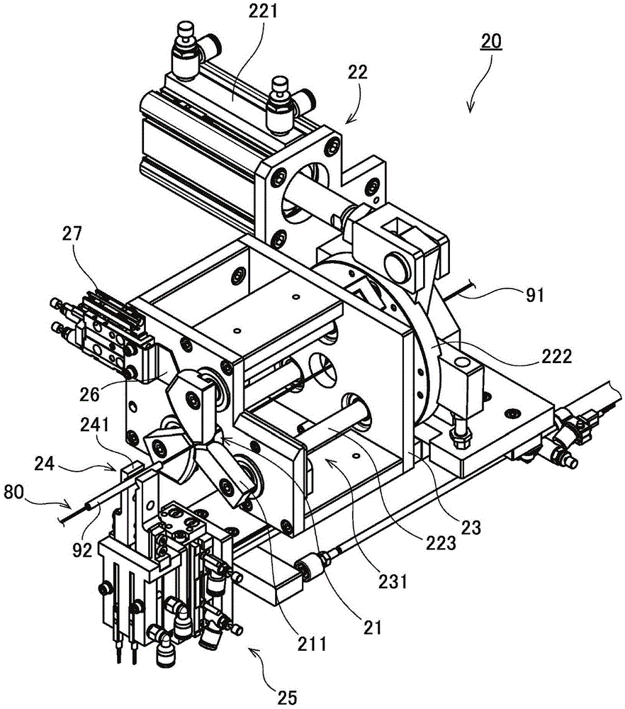
[0069] The insulating tube stopper 26 is a substantially plate-shaped member disposed between the guide portion 21 and the housing 23 . For example, metal such as iron is used as the material of the insulating tube stopper 26 . like Figure 8 As shown, the insulating tube stopper 26 of this embodiment extends horizontally from the vicinity of the supply path 80 along the surface of the housing 23 on the side of the guide portion 21 . and, if Figure 10 As shown, the insulating tube stopper 26 includes a plurality of walls 28 and a space 29 between the plurality of walls 28 . All of the plurality of wall surfaces 28 are opposed to the side surfaces of the conducting wire 91 .

[0070] In this embodiment, the insulating tube stopper 26 has a first wall surface 281 and a second wall surface 282 as the plurality of wall surfaces 28 . The first wall surf...


PUM


Abstract

The invention provides a coiling device and a coiling method. The coiling device comprises an insulating pipe stopper which has a cutting port toward a feeding path of a wire rod. The width of the cutting port is smaller than the external diameter of an insulating pipe. The coiling device enables the feeding path and the insulating pipe stopper to move relative to each other between an approaching state of the wire rod passing through the cutting port and a withdrawing state of the wire rod passing by the outside of an opening end of the cutting port. In the approaching state, the insulating pipe stopper and the downstream end portion of the insulating pipe contact to stop the insulating pipe. In the withdrawing state, the insulating pipe is sent to the downstream side. Therefore, the insulating pipe can be configured in an expected position. Moreover, the width of the cutting port of the insulating pipe stopper keeps unchanged. The insulating pipe really can be stopped instead of being stopped through approaching of multiple parts.

Description

technical field [0001] The invention relates to a winding device and a winding method. Background technique [0002] Conventionally, in the manufacturing process of a motor, a coil of an armature is formed using a winding device. In the wire winding device, a wire is wound around an iron core made of a magnet. In particular, in recent years, in order to efficiently perform the winding operation, a circular-shaped iron core is divided into a plurality of pieces, and a winding device for winding a conductive wire to each divided iron core has been proposed. [0003] For example, Japanese Laid-Open Patent Publication No. 2010-259212 describes a conventional winding device for winding a conductive wire around a split iron core. In the device described in this gazette, two bobbins injection-molded on the core sheet are attached to a main shaft, and the wire is supplied and wound while the main shaft is rotated. [0004] If the conducting wire is continuously wound around a plu...

Claims


Application Information

Patent Timeline
Patent Type & Authority Patents(China)
IPC IPC(8): H01F41/066H01F41/096H02K15/04
Inventor 谷口公大石谷明
Owner NIDEC MACHINERY
Why Eureka
Try Eureka