Wheel for track
A wheel and rail technology, applied in the field of rail wheels, can solve the problems of only being used in two-axle bogies and not being widely used, and achieve the effects of reducing derailment coefficient, improving service life and huge economic benefits.
- Summary
- Abstract
- Description
- Claims
- Application Information
AI Technical Summary
Problems solved by technology
Method used
Image

Examples
Embodiment approach 1
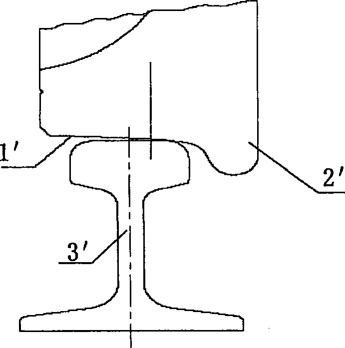
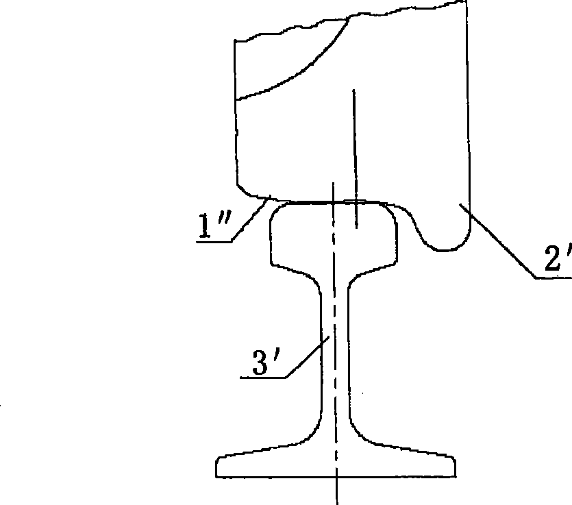
[0032] Please see first Figure 4 , which is a schematic diagram of a track wheel with a rotating rim according to the present invention. The track wheel with rotating rim of the present invention includes three parts, one part is the wheel body 1 , the other part is the rim 2 , and the third part is the rib 3 . The outer circumference of the wheel body 1 forms a tread 11 in contact with the track, and one side of the wheel body 1 is provided with a rim 2 whose outer diameter is larger than that of the tread 11. In this embodiment, the wheel The rim 2 is arranged on the inner side of the wheel body 1, wherein the rim 2 and the wheel body 1 are of a split structure, and the rim 2 is detachably and rotatably arranged on the outer circumference of the wheel body 1. In this embodiment, a reduced-diameter portion 12 with a diameter smaller than that of the tread surface 11 is provided at the inner end of the wheel body 1 , and the wheel rim 2 is rotatably sleeved on the reduced-di...
Embodiment approach 2
[0043] When the hardness of the material of the rim 2 is lower than that of the wheel body 1, in order to reduce the wear between the contact surface of the rim 2 and the wheel body 1, in addition to adopting the above-mentioned embodiment in which rolling elements 4 are arranged therebetween, as shown in Figure 10 As shown, a wear-resistant gasket 21 can also be provided at least between the wheel rim 2 and the wheel body 1 , for example, a nylon gasket can be provided to improve the wear-resistant performance of the wheel rim 2 . Nylon gaskets can also be arranged between the wheel rim 2 and the rib 3 to further improve the wear resistance between the wheel rim and the rib.
[0044] Other structures, working principles, and beneficial effects of this embodiment are the same as those of Embodiment 1, and will not be repeated here.
Embodiment approach 3
[0046] In this embodiment, a wear-resistant coating (not shown) is provided on the side of the wheel rim 2 at least facing the wheel body 1. In order to improve the overall wear resistance of the wheel rim 2, the side facing the wheel body 1 can be Both sides of the wheel body 1 and the rib 3 are provided with wear-resistant coatings. The wear-resistant coating can be, for example, a composite layer or a coating layer. For example, a tungsten carbide layer or chrome plating can be applied on the rim 2 to strengthen the surface hardness of the rim 2 and improve wear resistance. And the wear-resistant coating can also be arranged on the wheel body facing the side of the rim. Compared with the above-mentioned arrangement of wear-resistant gaskets, this embodiment reduces the number of parts and facilitates assembly.
[0047] Other structures, working principles, and beneficial effects of this embodiment are the same as those of Embodiment 1, and will not be repeated here.
PUM
 Abstract
Description
Claims
Application Information
 - R&D
- Intellectual Property
- Life Sciences
- Materials
- Tech Scout
- Unparalleled Data Quality
- Higher Quality Content
- 60% Fewer Hallucinations
Browse by: Latest US Patents, China's latest patents, Technical Efficacy Thesaurus, Application Domain, Technology Topic, Popular Technical Reports.
© 2025 PatSnap. All rights reserved.Legal|Privacy policy|Modern Slavery Act Transparency Statement|Sitemap|About US| Contact US: help@patsnap.com