Volume fluid machine and piston producing method thereof

A fluid machinery, volumetric technology, applied in liquid variable volume machinery, components of pumping devices for elastic fluids, rotary piston machinery, etc., can solve the problem of balance deterioration, increased pressure loss, short shaft rotation angle, etc. question

Inactive Publication Date: 2007-03-07
HITACHI LTD
View PDF8 Cites 0 Cited by
  • Summary
  • Abstract
  • Description
  • Claims
  • Application Information

AI Technical Summary

Problems solved by technology

[0009] However, since the stroke (about half of the rotary type, the same as the reciprocating type) from the end of suction to the end of discharge of each working chamber formed by several vanes and cylinders constituting the piston is short, the shaft rotation angle θc is about 180° ( 210°), so there is a problem that the flow rate of the fluid is fast during the discharge process, the pressure loss increases, and the performance decreases
In addition, in the fluid machines disclosed in these documents, since the shaft rotation angle from the end of suction to the end of dis...

Method used


Image

  • Volume fluid machine and piston producing method thereof
  • Volume fluid machine and piston producing method thereof
  • Volume fluid machine and piston producing method thereof

Examples


Embodiment Construction

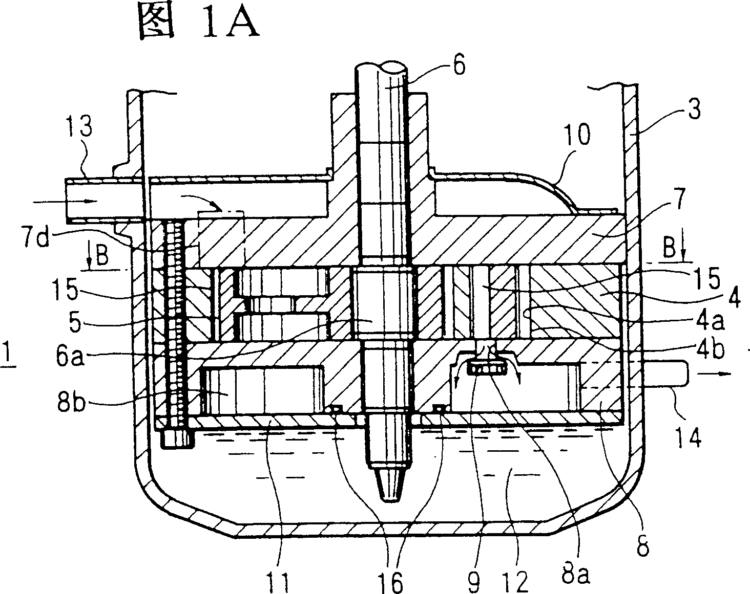
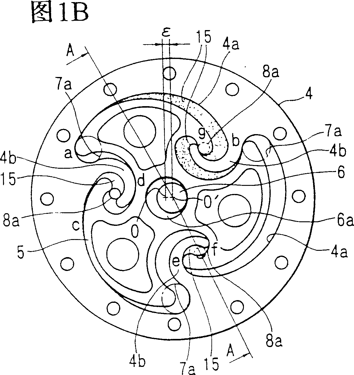
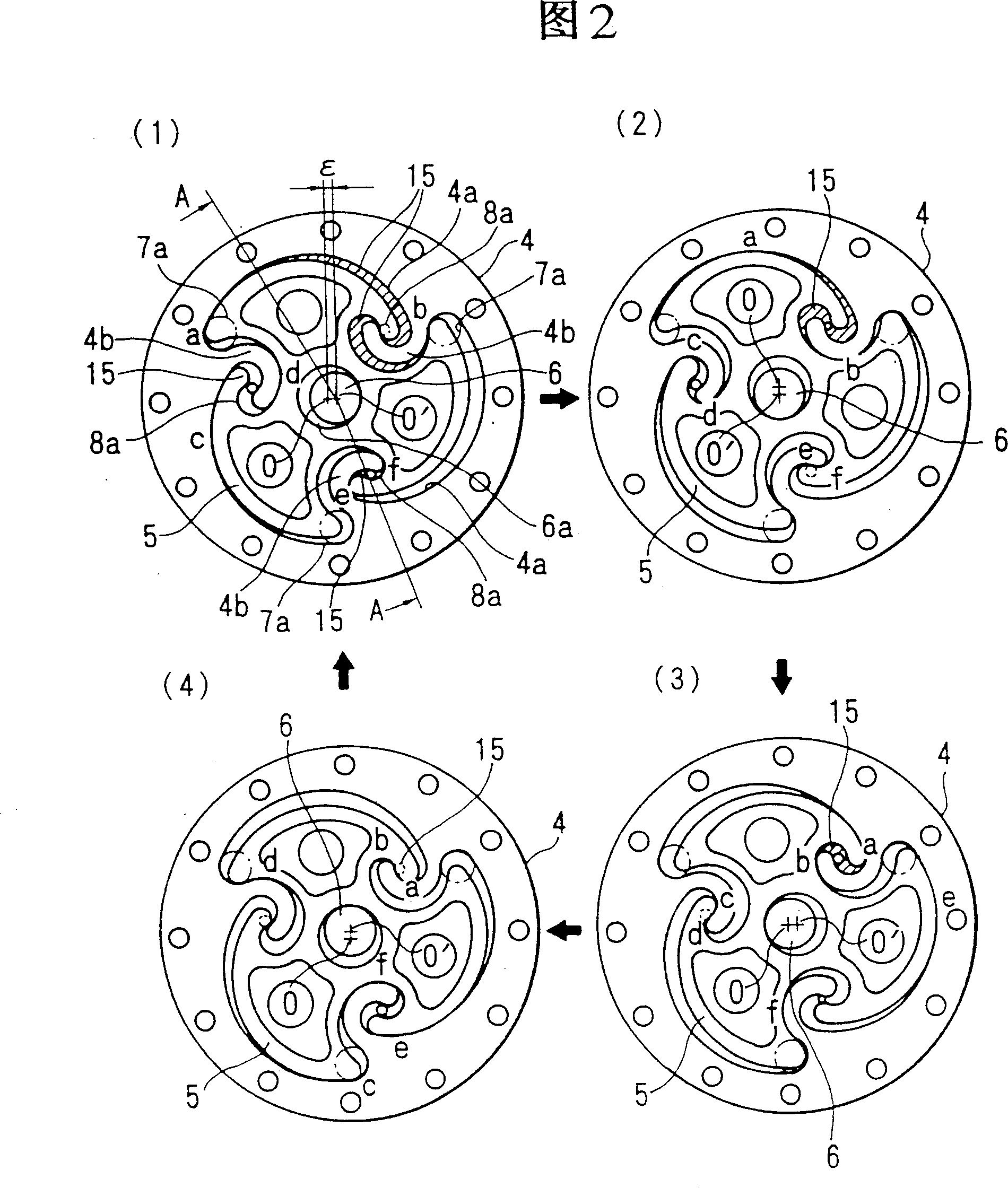
[0044] The characteristics of the present invention described above will be more clear through the following examples. An embodiment of the present invention will be described below with reference to the drawings. First, the structure of the rotary fluid machine of the present invention will be described using FIGS. 1 to 3 . Fig. 1 (A) is the longitudinal sectional view (the A-A sectional view of (B)) of the hermetic compressor when using the volumetric fluid machine of the present invention as a compressor, (B) is the B-B sectional view of (A), the figure 2 is a working principle diagram of a positive displacement compression mechanism, and FIG. 3 is a longitudinal sectional view of a hermetic compressor when the positive displacement fluid machine of the present invention is used as a compressor.

[0045] As shown in FIG. 1 , a volumetric compression mechanism 1 of the present invention and an electric mechanism 2 (not shown) for driving the compression mechanism are instal...


PUM


Abstract

This invention is related to a volumetric fluid compressor, for providing a volumetric fluid machine that has pressure loss is minimized to be as low as a rotary fluid compressor in the process of discharging, and that can be manufactured in an manner that is easier than that of making a spiral fluid compressor. To solution is, within a hollow cylinder having a cross-section constructed of plural curves, letting the rotation angle c of the spindle caused by the moving fluid discharged by the plural outlets, during each compression stroke of individual operation chambers of the volumetric fluid compressor, to be (((N-1)/N) x 360 DEG) < c < 360 DEG, (where N is the number of strips).

Description

[0001] This application is a divisional application of the application No. 97103149.5, the filing date is January 31, 1997, and the invention name is "volumetric fluid machine". technical field [0002] The present invention relates to eg pumps, compressors, expanders etc., and in particular to positive displacement fluid machines. Background technique [0003] As a conventional volumetric fluid machine, for example, a reciprocating fluid machine in which a piston repeatedly reciprocates in a cylindrical cylinder to make the working fluid flow, and a cylindrical piston in a cylindrical cylinder eccentrically rotates. Rotary type (rotary piston type) fluid machine that makes working fluid flow, orbiting the orbiting scroll by engaging a pair of fixed scrolls with spiral scrolls standing upright on the end plate and the orbiting scroll And the scroll type fluid machine that drives working fluid to flow is already known technology. [0004] The advantage of reciprocating fluid...

Claims


Application Information

Patent Timeline
IPC IPC(8): F04C18/02F04C29/00B23Q3/18F01C1/02F01C1/04F01C1/06F04BF04C18/06F04C18/10F04C18/22
CPCF01C1/06F04C18/06
Inventor 香兽我部弘胜竹林昌宽畠裕章稻场恒一早濑功东条健司
Owner HITACHI LTD
Why Eureka
Try Eureka