Sealing structure and device with the sealing structure

A sealing structure and valve device technology, which is applied to the surface coating liquid device, shaft seal, valve device, etc., can solve problems such as poor movement and inability to move, and achieve the effect of solving heat or wear and easy assembly and disassembly

Active Publication Date: 2022-04-29
MUSASHI ENG INC
View PDF4 Cites 0 Cited by
  • Summary
  • Abstract
  • Description
  • Claims
  • Application Information

AI Technical Summary

Problems solved by technology

The reason for this is that if the fluid enters the drive chamber, it will cause a malfunction, and in the worst case, it may cause a malfunction.

Method used


Image

  • Sealing structure and device with the sealing structure
  • Sealing structure and device with the sealing structure
  • Sealing structure and device with the sealing structure

Examples


no. 1 Embodiment approach

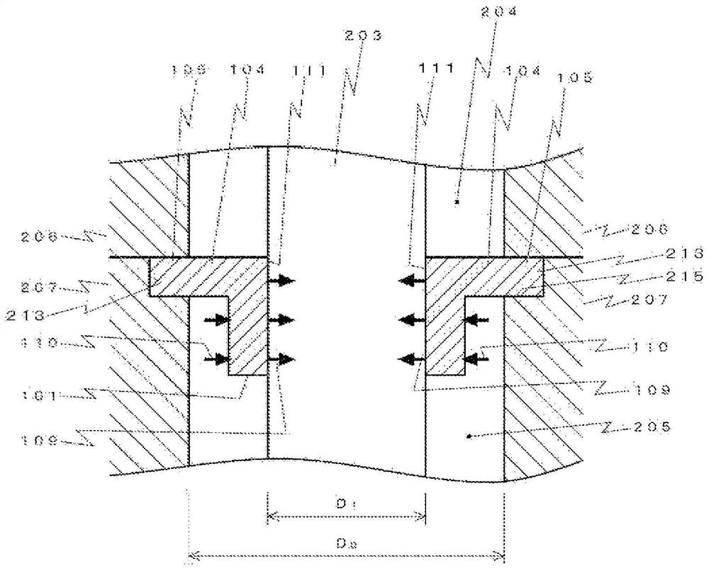
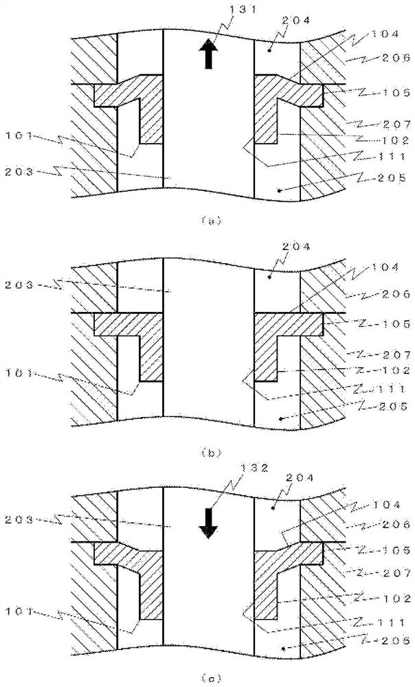
[0043] The seal structure according to the first embodiment is configured to include a seal 101 , upper and lower case members ( 206 , 207 ) in which a fluid chamber 205 is formed, and a needle 203 .

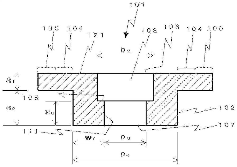
[0044] Such as figure 1 As shown, the sealing member 101 is composed of a cylindrical main body 102, a through-hole 103 formed to pass through the main body 102 and having a different inner diameter on the upper side and the lower side, and a convex hole formed on the outer periphery of the main body 102. The flange part (104, 105) constitutes.

[0045] The main body 102 is a cylindrical member, and extends in a direction parallel to the needle 203 (ie, in an up-down direction). The length of the main body 102 (H 1 +H 2 ) is, for example, 2 to 4 mm, and from another point of view, it is the thickness H of the flange portion (104, 105) 1 (or the thickness W of the through-hole sidewall 111 1 ) of, for example, 2 to 5 times. By setting the length of the main body 102 (H 1 +...


PUM


Abstract

The technical problem of the present invention is to provide a sealing structure in which the needle and the sealing member do not slide and are easy to attach and detach, and a device provided with the sealing structure. A sealing member, a sealing structure provided with the sealing member, and a device provided with the sealing structure, the sealing member being used for a valve device provided with a fluid chamber having an outflow hole and an inflow hole, and a needle whose tip reciprocates in the fluid chamber The needle insertion seal includes: a main body formed with a needle insertion hole into which the needle is inserted and made of an elastic body; and a flange extending annularly from the main body radially outward. And it is made of elastic body; the opening diameter of one end of the above-mentioned needle insertion hole (D 3 ) is smaller than the opening diameter of the other end of the needle insertion hole (D 2 ).

Description

technical field [0001] The present invention relates to a sealing structure and a device provided with the sealing structure. Background technique [0002] In the needle valve, in order to prevent fluid from entering the drive chamber from the fluid chamber, the needle is provided with a seal structure that separates the fluid chamber from the drive chamber. The reason for this is that if the fluid enters the drive chamber, malfunction may occur, and in the worst case, the operation may not be possible. [0003] As a sealing structure, an O-ring is generally used, but in order to improve sealing performance, a rod seal in which a needle slides in a through hole (for example, Patent Document 1) or a diaphragm (for example, Patent Document 2) may be used. [0004] As an example using a stem seal, there is disclosed in Patent Document 1 an applicator that discharges liquid a small amount at a time by reciprocating movement of the valve stem, and a pair of dynamic seals (90, 92...

Claims


Application Information

Patent Timeline
Patent Type & Authority Patents(China)
IPC IPC(8): F16J15/18B05C5/00F16J15/24F16J15/48F16K1/32
CPCF16J15/18F16J15/24F16J15/48F16K1/00F16K1/32F16J15/52F16K1/46B05C5/0225B05C11/1026B05C11/10B05C5/00B05B1/3046F16K41/04
Inventor 生岛和正
Owner MUSASHI ENG INC
Why Eureka
Try Eureka