
Microwave sensing for determination of loading of filters

A filter and microwave technology, used in instruments, measuring devices, measuring electrical variables, etc., can solve the problems of limited fatigue life of filters, large thermal stress, high temperature, etc.

Inactive Publication Date: 2009-05-20
MASSACHUSETTS INST OF TECH
View PDF5 Cites 13 Cited by
  • Summary
  • Abstract
  • Description
  • Claims
  • Application Information

AI Technical Summary

Problems solved by technology

Under certain conditions, regeneration has the potential to generate very high temperatures leading to high thermal stresses which can lead to limited fatigue life and eventual destruction of the filter

Method used


Image

  • Microwave sensing for determination of loading of filters
  • Microwave sensing for determination of loading of filters
  • Microwave sensing for determination of loading of filters

Examples


Embodiment Construction

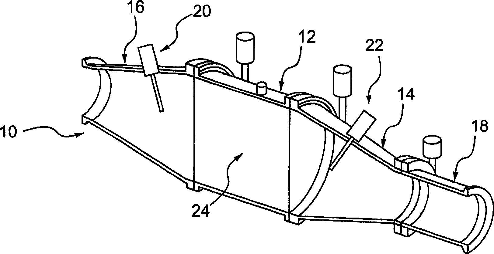
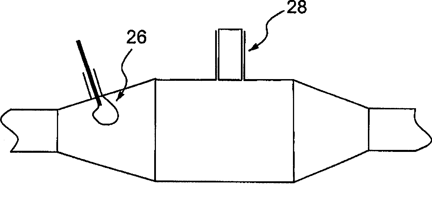
[0018] The invention is based on the insight that microwaves can be used to determine the state of the load of a collector or filter. The load can be soot, particulate, ash or any solid / liquid. In addition to determining the total load, the microwave system that will be described herein can also be used to determine the distribution of the load throughout the collector. Microwave sensing used in the present invention can be relatively inexpensive since inexpensive oscillators and detectors are commercially available in the frequency range of interest.

[0019] In the case of a diesel particulate filter, the particulates consist of soot and other organic compounds (solid and / or liquid) and ash. For the purposes of this invention, the combination of carbon, organic compounds, and ash will be referred to (for simplicity) as soot. Those skilled in the art will recognize that soot and organic compounds are removed by regeneration, but the ash load will still be present.

[0020]...


PUM


Abstract

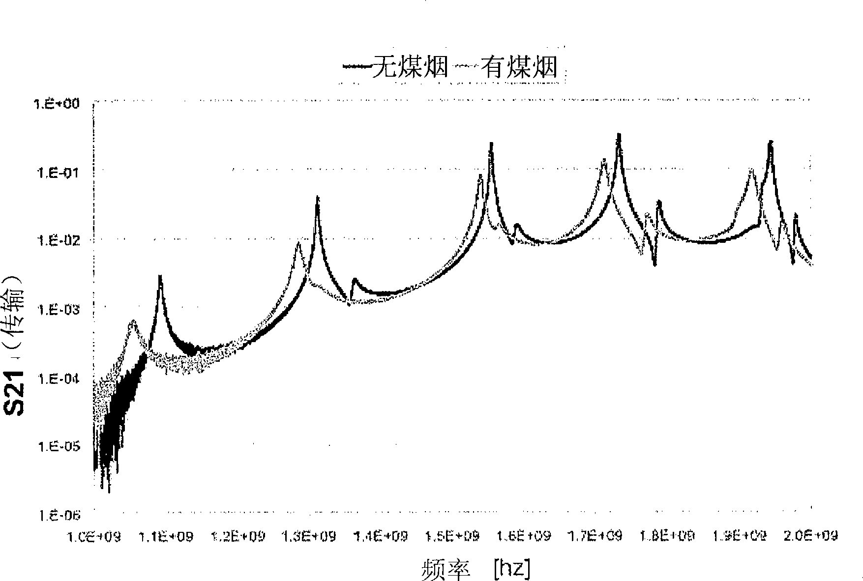
Method for determining loading of a filter. The filter has a first dielectric constant. The filter becomes loaded with contaminant material that has a second dielectric constant. The filter, such as a diesel particulate filter, is contained within a metallic enclosure forming a microwave cavity. The method includes establishing microwave energy in the cavity and monitoring changes in the cavity microwave response, the changes being related to filter loading.

Description

[0001] This application claims priority to Provisional Application No. 60 / 746,081, filed May 1, 2006, the contents of which are incorporated herein by reference. technical field [0002] The present invention relates to the determination of filter loading, and more particularly to the use of microwave sensing to determine filter loading. Background technique [0003] In many fields, there is a need to accurately sense the amount of material that a filter has captured. One example is the need to determine filter loading of soot on a diesel particulate filter (DPF). In order to determine the proper conditions for regeneration initiation and to monitor conditions to determine when complete regeneration has been achieved, the load on the diesel particulate filter must be known. The load level is important in this scenario because the regeneration of the DPF is usually by uncontrolled combustion where the soot is ignited by the presence of free oxygen and passes through the filt...

Claims


Application Information

Patent Timeline
Patent Type & Authority Applications(China)
IPC IPC(8): G01R27/04
CPCF01N2900/1611F01N2370/22F01N2900/1606F01N2560/05F01N2560/14Y02T10/47F01N9/002F01N2560/12Y02T10/40
Inventor 莱斯利·布朗伯格亚历克斯·萨波克罗纳德·帕克维克托·王彼得·薛尔特
Owner MASSACHUSETTS INST OF TECH
Learn More