
Brake caliper

A technology of brake calipers and disc brakes, applied in the field of brake calipers, can solve problems such as increased fuel consumption, small return movement, insufficient return of pistons and brake linings, etc., to achieve optimized air gap performance, optimized The effect of kinematic performance and deformation performance

Active Publication Date: 2009-05-20
CONTINENTAL AUTOMOTIVE TECH GMBH
View PDF1 Cites 4 Cited by
  • Summary
  • Abstract
  • Description
  • Claims
  • Application Information

AI Technical Summary

Problems solved by technology

It has been shown that the sealing structure has a significant impact on comfort and brake lining and friction due to the insufficient return of the piston to the brake lining and the inability to create a sufficient air gap between the brake lining and the brake disc. Significant disadvantages in terms of ring wear
As the brake pads are pressed against the disc when the disc is not actuated, a residual torque is generated, which increases fuel consumption, generates noise and causes excessive wear of the brake pads and friction rings
Said disadvantage is particularly serious when the brake is actuated mechanically, since the return movement produced by the sealing ring is small

Method used


Image

  • Brake caliper
  • Brake caliper
  • Brake caliper

Examples


Embodiment Construction

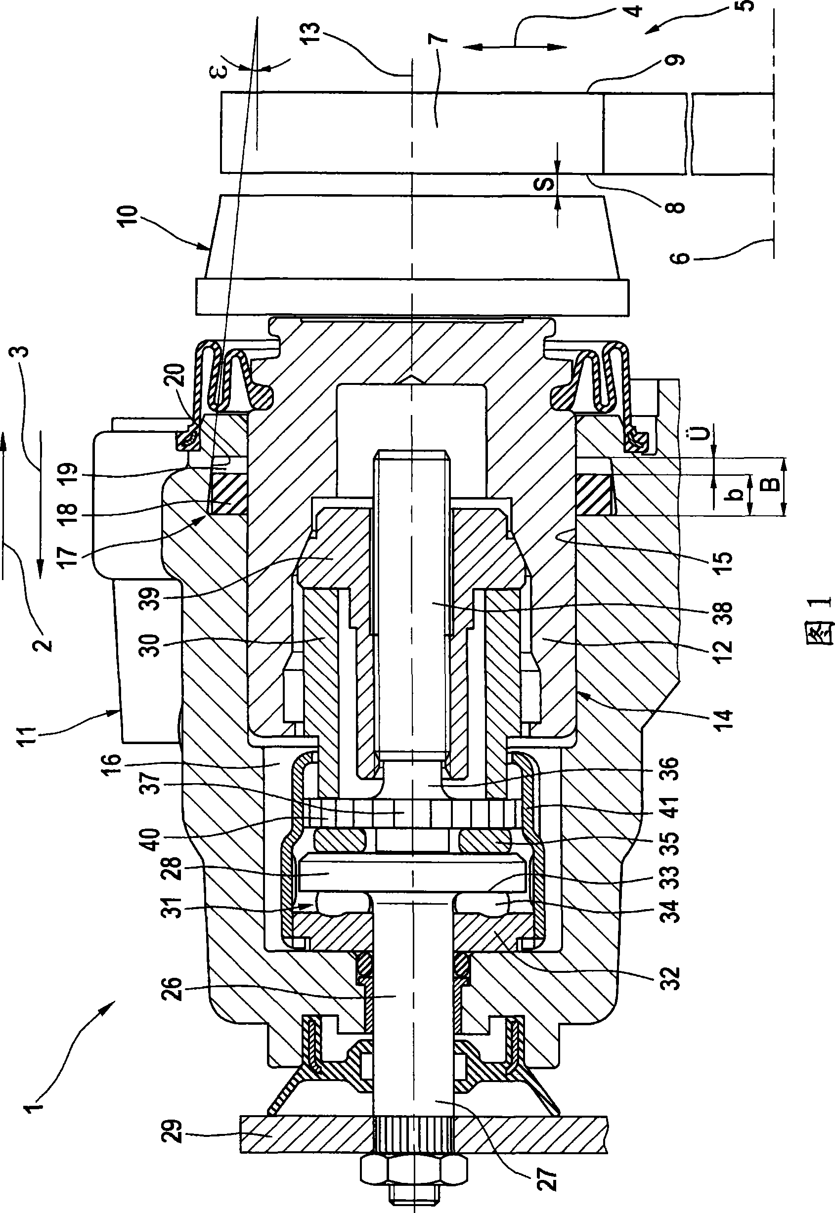
[0018] FIG. 1 shows a disc brake with a brake caliper 1 , a brake lining 10 and a brake disc 5 , only the parts of these components relevant to the invention being shown. The brake caliper 1 itself comprises a caliper housing 11 and a piston 12 arranged to be movable in a bore 14 along the bore axis for braking operation. By displacing the piston 12 in the direction of application of pressure, the piston 12 pushes the brake lining 10 against the axial friction surface 8 of the friction ring 7 of the brake disk 5 . The brake disk 5 is mounted pivotably about a pivot axis 6 . Shelled bridge not shown ( ), the housing bridge extends beyond the brake disc 5 so that the other axial friction surface 9 of the friction ring 7 can be loaded by means of another brake lining.

[0019] In the case of service braking, the displacement piston 12 is acted upon by means of hydraulic pressure. For this purpose, the piston 12 and the caliper housing 11 form a pressure chamber 16 in which a ...


PUM


Abstract

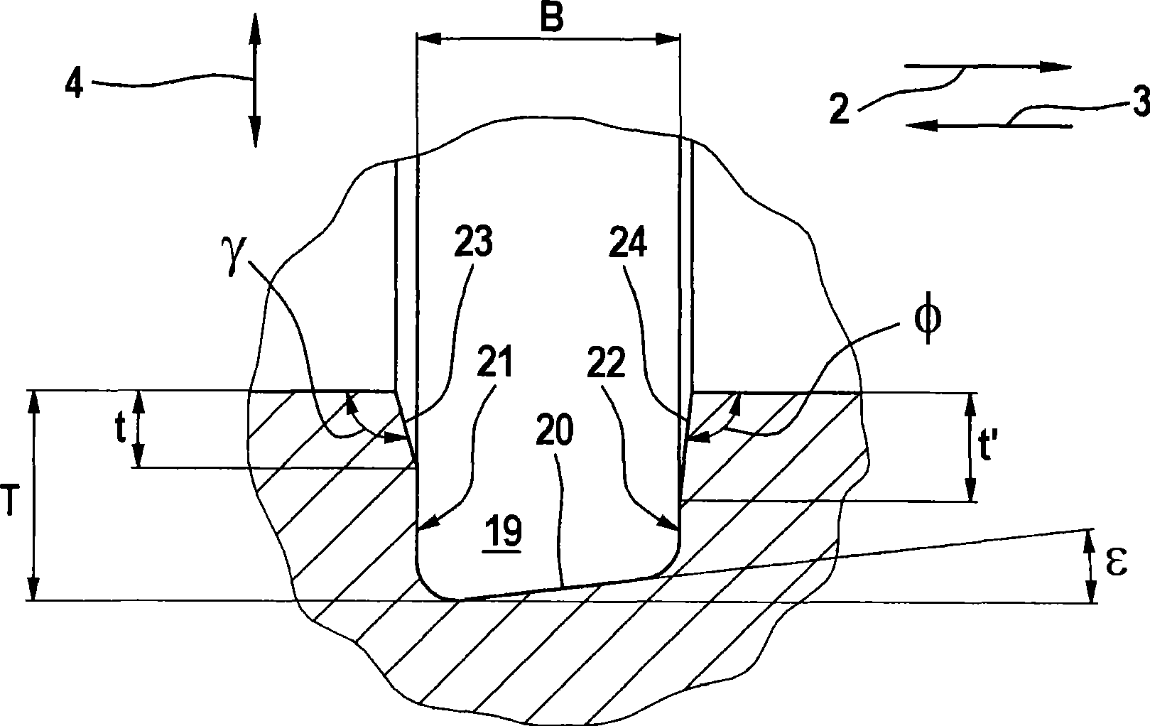
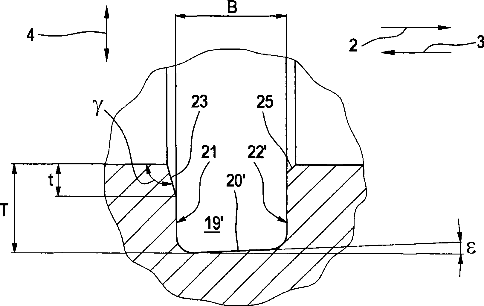
The invention relates to a brake caliper (1) for a disk brake with a caliper housing, in which there is an actuating device with a piston (12) in a bore (14). This piston (12) is movable in the bore (14) along a bore axis (13), wherein motion is possible in both an actuation direction and in a release direction. There is a seal system (17) between the piston (12) and the bore (14), with a gasket ring (18) in a radial groove (19). A problem addressed by the invention is to provide a brake caliper for a disk brake with an actuating device that avoids the drawbacks of the prior art and especially achieves effective resetting of the piston after actuation of the brake. According to the invention the problem is solved with the features of the characterizing part of claim 1, wherein a groove bottom (20,20') of the groove (19) is arranged in the direction of the bore axis (13) and anti-parallel to the bore axis (13) so that in the brake actuation direction the groove bottom (20,20') approaches the bore axis (13).

Description

technical field [0001] The invention relates to a brake caliper for a disc brake having a caliper housing in which an actuating mechanism is arranged, the actuating mechanism having a piston arranged in a bore. The piston is supported displaceably within the bore along the bore axis, wherein it is displaceable in a pressing direction and a return direction. A sealing structure is arranged between the hole and the piston, and the sealing structure has a sealing ring arranged in a radial groove. Background technique [0002] EP 0 403 635 B1 discloses such a disc brake caliper. Therein a hybrid brake caliper for a vehicle disc brake is proposed, the brake caliper comprising a caliper housing in a bore in which a piston for actuating the braking operation is movably arranged. In order to provide the parking brake function, a shaft is pivotally mounted in the caliper housing, wherein the shaft projects out of the caliper housing and is connected to a ramp element of a ramp arra...

Claims


Application Information

Patent Timeline
Patent Type & Authority Applications(China)
IPC IPC(8): F16D65/20F16J15/16F16D65/18
Inventor W·朗格H·奥尔姆斯T·阿达姆F·斯特雷茨
Owner CONTINENTAL AUTOMOTIVE TECH GMBH
Learn More