Lens drive device and coil winding method

A technology of lens drive device and winding direction, which is applied in coils, coil manufacturing, movable winding electromagnets, etc., can solve problems such as easy loosening, achieve the effects of preventing loosening, shortening winding time, and improving work efficiency

Inactive Publication Date: 2009-05-20
NIDEC SANKYO CORP
View PDF1 Cites 14 Cited by
  • Summary
  • Abstract
  • Description
  • Claims
  • Application Information

AI Technical Summary

Problems solved by technology

On the contrary, if the winding is performed from the upper section first, the initial part of the winding becomes easy to loosen.
This problem also arises in configurations where the coil is not divided into two segments up and down

Method used


Image

  • Lens drive device and coil winding method
  • Lens drive device and coil winding method
  • Lens drive device and coil winding method

Examples


Embodiment Construction

[0044] The best mode for carrying out the present invention will be described below with reference to the drawings.

[0045] [Mechanical structure]

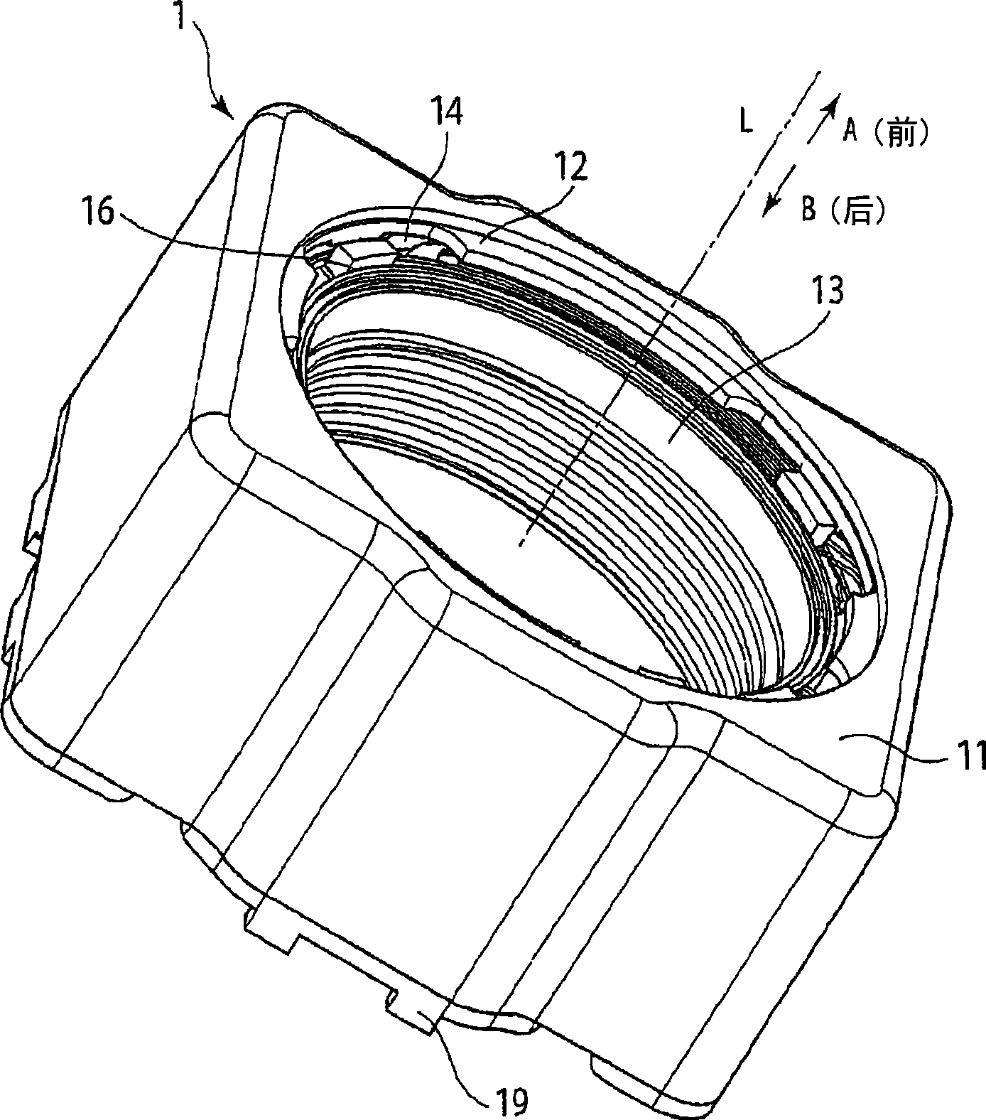
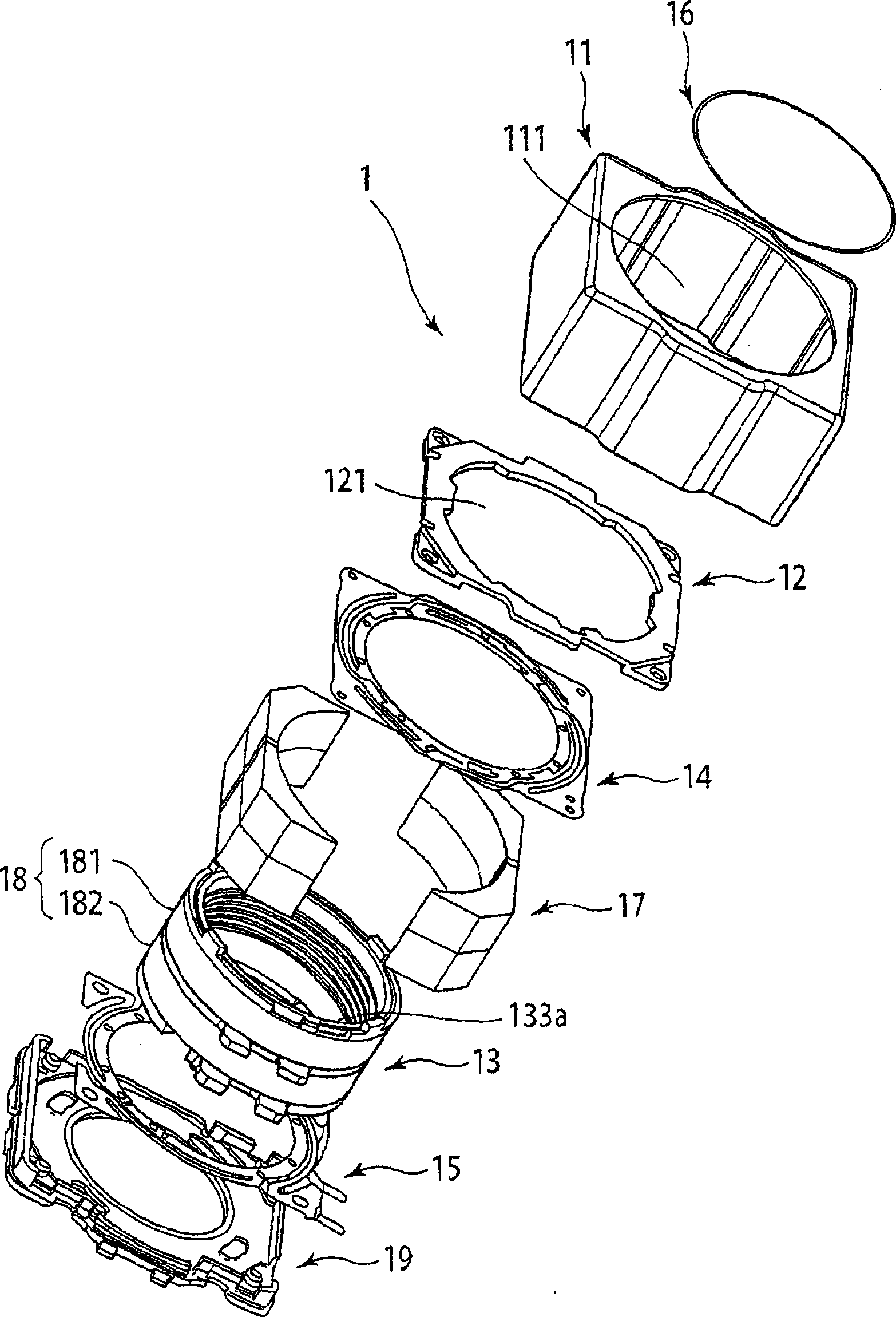
[0046] figure 1 It is a perspective view showing the external structure of the lens driving device 1 according to the embodiment of the present invention. figure 2 It is an exploded perspective view showing the mechanical structure of the lens driving device 1 according to the embodiment of the present invention.

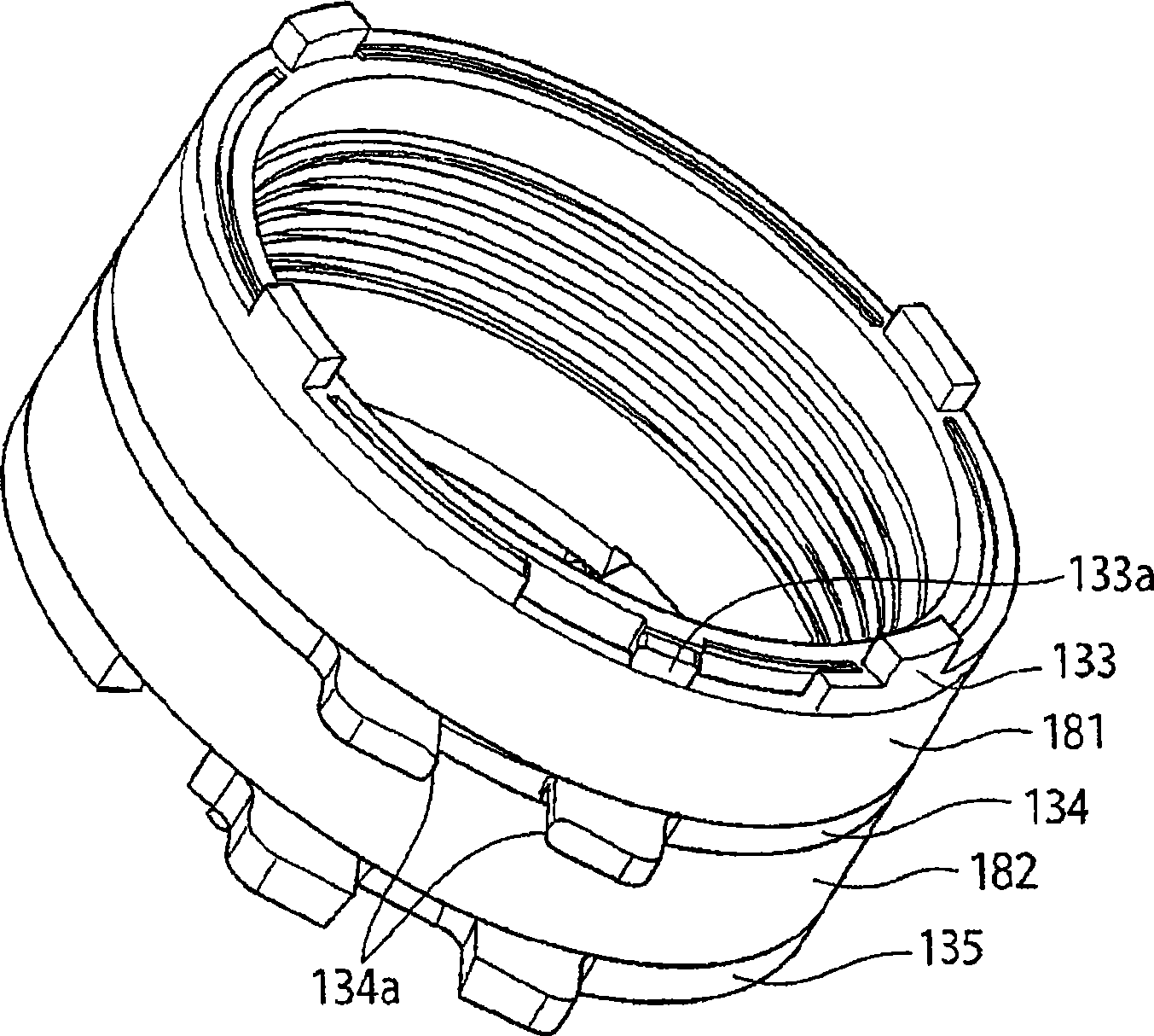
[0047] exist figure 1 and figure 2 Among them, the lens driving device 1 has: a yoke 11, a cover 12, a sleeve 13, a first leaf spring 14, a second leaf spring 15, a wire spring 16, a magnet 17, and a coil 18 (the first coil 181 and the second coil 182 ), and holder 19.

[0048] In addition, the lens barrel on which the lens is mounted is not shown. The lens driving device 1 directs the sleeve 13 toward the A direction (front side) close to the object (image-taking object) and the B direction (rear side) close t...


PUM


Abstract

A lens drive device and a coil winding method may prevent loose of the coil. The lens drive device (1) includes a movable body (sleeve 13) movable in an optical axis direction, a support body (maintaining element 19) supporting the movable body through a spring member and a magnetic drive mechanism having a coil (18) and driving the movably body along the optical axis. The movable body includes a coil winding part (131, 132) wherein the coil is winded, an end part and the other end part (a first end part 133, a third end part 135) for restricting a range of the coil winding part and a changing part (133a) formed on at least an end part of the end parts and for changing a drawing direction of the coil (18). The spring member is disposed near the end part except the end part where the changing part (133a) is formed. The winding start and finish ends of the coil (18) are connected electrically.

Description

technical field [0001] The invention relates to a lens driving device and a coil winding method for driving a lens to displace along an optical axis to image an object. Background technique [0002] In recent years, along with the popularization of mobile phones with cameras equipped with cameras, opportunities to use such mobile phones to photograph various subjects are increasing. For example, you may shoot a subject that is a certain distance from the camera lens, such as a friend or a landscape (normal shooting), or take a picture of a subject that is close to the camera lens, such as a bus timetable or flower petals ( low magnification). [0003] In macro shooting, the lens position of the camera needs to be located slightly closer to the subject side than the lens position in normal shooting. Therefore, such an imaging lens system includes a driving mechanism for driving the lens to displace along the optical axis, and the driving mechanism can be driven by switching...

Claims


Application Information

Patent Timeline
IPC IPC(8): G02B7/02G02B7/04H01F41/06H01F5/00
CPCG02B7/08H01F7/066
Inventor 武居勇一樋口大辅须江猛
Owner NIDEC SANKYO CORP
Why Eureka
Try Eureka