Thyristor direct switching on-load tap-changer

An on-load tap, thyristor technology, applied in electronic switches, transformers, electrical components, etc., can solve the problems of poor fast performance, large maintenance, low reliability, etc., and achieve the effect of high fast performance

Active Publication Date: 2011-02-16
SHANGHAI HUAMING POWER EQUIP CO LTD +1
View PDF0 Cites 0 Cited by
  • Summary
  • Abstract
  • Description
  • Claims
  • Application Information

AI Technical Summary

Problems solved by technology

[0009] The technical problem to be solved by the present invention is to provide a group of thyristors to directly switch on-load tap-changers to solve the problems of traditional on-load tap-changers such as arcing during on-load breaking, short electrical life, poor fast performance, and poor reliability. Problems such as low cost and high maintenance

Method used


Image

  • Thyristor direct switching on-load tap-changer
  • Thyristor direct switching on-load tap-changer
  • Thyristor direct switching on-load tap-changer

Examples


Embodiment 1

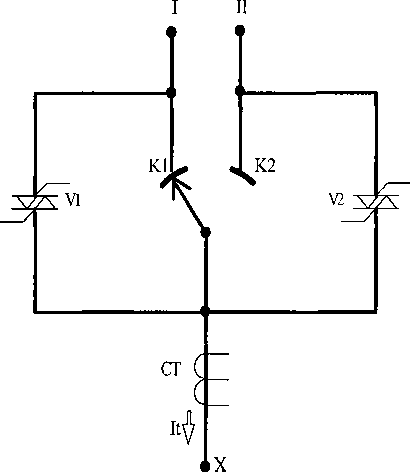
[0022] What this embodiment is going to explain is that the thyristor direct switching on-load tap-changer is a thyristor combined direct switching on-load tap-changer, and its switching circuit includes a thyristor direct switching that realizes current switching between taps when the transformer current crosses zero. circuit.

[0023] see figure 1 , Thyristor direct switching circuits are connected to the fixed contacts of odd-numbered taps and even-numbered taps. When switching, the gate circuit of the newly tapped thyristor switch must be connected at a moment near the zero crossing point of the transformer current; the original tap must be disconnected before the zero crossing point (in this embodiment, at a time near the 90° electrical angle). The gate circuit of the upper thyristor. To do this, it is necessary to detect the zero crossing of the transformer current and to control the gate of the thyristor with an electronic switch. In this embodiment, a current transf...

Embodiment 2

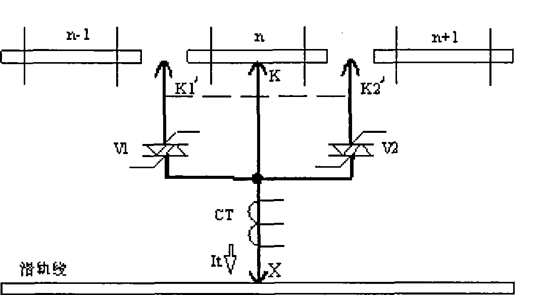
[0035] What this embodiment is going to explain is the thyristor compound type direct switching on-load tap-changer (see figure 2 ). A thyristor switch branch is connected to the two transition moving contacts. During the switching process, when the moving contact has moved to one transition moving contact and the original tap fixed contact, and the thyristor on the branch passes through the current of the transformer; the other transition moving contact connects to the new tap Switching can be performed when the fixed contact is connected but the thyristor on the branch is not connected. When switching, the gate circuit of the newly tapped thyristor switch must be connected at a moment near the zero crossing point of the transformer current; the original tap must be disconnected before the zero crossing point (in this embodiment, at a time near the 90° electrical angle). The gate circuit of the upper thyristor switch.

[0036] see figure 2 , in order to achieve the abov...


PUM


Abstract

The invention provides a thyristor direct shifting on-load tap-changer, comprising a shifting switch circuit; the thyristor direct shifting on-load tap-changer is characterized in that the shifting switch circuit comprises a thyristor direct shifting circuit which realizes the tapping current shifting when the current of the transformer is over zero point. The thyristor direct shifting on-load tap-changer turns off the load current of original tapping and turns on the load current of the new tapping at the same over-zero point of the current of the transformer, generates no electric arcs, andhas no problem that the contact of the switch is burned by the electric arc; the service life of a shifting switch is not restricted by the shifting times; the thyristor direct shifting on-load tap-changer has high quick performance, provides low temperature environment for other elements, has no problem that the transformer oil in a switch oil chamber turns bad as being burned by the shifting electric arc, lightens the workload of oil filtration and oil change of the transformer, and saves the oil; the shifting switch and the transformer can commonly use an oil tank.

Description

Background technique [0001] The invention relates to the technical field of transformer on-load tap-changers, in particular to a thyristor directly switching on-load tap-changer. Background technique [0002] On-load tap-changers are an important component of power tap-changing transformers and industrial tap-changing transformers. When the transformer does not interrupt the load current (that is, under load), the tap is adjusted to change the turns ratio of the transformer, thereby adjusting the output voltage of the transformer. [0003] Since the on-load tap-changer was successfully developed by Americans and Germans more than 80 years ago, it is basically a traditional mechanical contact product that uses mechanical switch contacts for switching. This type of on-load tap-changer product exists as follows question: [0004] 1. The mechanical contacts of the diverter switch produce arcs when they are disconnected under load, which is likely to cause contact burnout and s...

Claims


Application Information

Patent Timeline
Patent Type & Authority Patents(China)
IPC IPC(8): H01F29/04H03K17/687
Inventor 肖日明肖毅肖申
Owner SHANGHAI HUAMING POWER EQUIP CO LTD
Why Eureka
Try Eureka