
Light source for projection system and projection display device

A light source device, projection display technology, applied in projection devices, lighting devices, components of lighting devices, etc., can solve the problem of low synthetic white light power, insufficient use of red light and blue light power, improve contrast and control costs, etc. It can improve the color saturation and contrast, solve the problem of insufficient green lighting, and improve the effective utilization rate.

Inactive Publication Date: 2009-05-13
PHOEBUS VISION OPTO ELECTRONICS TECH +1
View PDF1 Cites 17 Cited by
  • Summary
  • Abstract
  • Description
  • Claims
  • Application Information

AI Technical Summary

Problems solved by technology

Due to the lack of green light power, the total light power is low due to its constraints, which is one of the important reasons for the insufficient brightness of the LED projection display.
The existing solution is to increase the time duty ratio of green light in the whole white light to increase the brightness. This method does not make full use of the optical power of red light and blue light; or reduce the optical power of red light and blue light to obtain White balance, this method leads to low optical power of synthetic white light due to the limitation of green light power
[0012] In short, the various light sources for projection display in the prior art have differences in the power ratio of red, green, and blue light and the white field requirements, so that the color saturation, brightness, and contrast are insufficient, and it is impossible to simultaneously improve color saturation and increase Combined effect of brightness, contrast enhancement and cost control

Method used


Image

  • Light source for projection system and projection display device
  • Light source for projection system and projection display device
  • Light source for projection system and projection display device

Examples


Embodiment Construction

[0042]Due to the small spot and divergence angle of the laser, the etendue of the laser is very small. The etendue of the laser output from the fiber is determined by the following formula:

[0043] E. laser = π 2 r 2 sin 2 θ

[0044] where r is the radius of the fiber bundle and sinθ is the numerical aperture of the fiber. A fiber optic bundle is formed by combining one or more optical fibers.

[0045] For example, for a fiber bundle radius of 0.35mm and a fiber bundle with a numerical aperture of 0.22, the etendue of the output laser is only 5.22×10 -2 mm 2 sr, compared with light-emitting diodes, is more than 2 orders of magnitude smaller. The luminous flux under this etendue can reach thousands to tens of thousands of lumens. Therefore, for a laser, a very small etendue can obtain a very high luminous flux output.

[0046] In a mixed light source of a light-emitting diode and a laser, set the etendue of the light-emitting diode to be E led , the etendue of the l...


PUM

PropertyMeasurementUnit
wavelengthaaaaaaaaaa

Abstract

The invention provides a light supply apparatus with high brightness, high contrast and high color saturation and projection display equipment which are used in a projection system. The light supply apparatus comprises a supplemental light source and a laser light source, and a reflecting mirror which synthesizes the light radiated by the supplemental light source and the laser radiated by the laser light source into a bunch. The reflecting mirror comprises a reflection part used for reflecting lasers radiated by the laser light source and a transmission part which light beams sent out by the supplemental light source can directly transmit and pass though. The invention skillfully leads the lasers of a laser device into the light bulb of the projection system and an LED illuminating source, can successfully adjust the intensity distribution of tricolor of red, green, and blue, increases the performance such as illumination, color saturation and contrast and the like, and has very high utility value in the projection display field.

Description

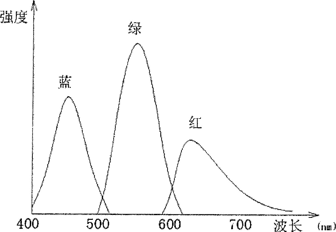
technical field [0001] The invention relates to a light source device and a projection display device, in particular to a light source device and a projection display device for a projection display system. Background technique [0002] Ultra-high pressure mercury lamps, metal halide lamps, xenon lamps, halogen lamps, etc. used in existing projection system lighting, the spectrum of these light sources is limited by the luminescent substance and its state, showing the characteristics of continuous or banded spectrum. Luminescence Spectrum of UHP Mercury Lamp figure 1 For example, as shown in the figure, red light has a wide band and a low peak value, and the intensity distribution of red, green and blue primary colors is not ideal, which cannot meet the requirements of white field color balance, so it cannot better meet the requirements of projection system lighting. At present, the prior art generally adopts a method of selecting a broad spectrum band to increase the lumin...

Claims


Application Information

Patent Timeline
Patent Type & Authority Applications(China)
IPC IPC(8): G03B21/20F21V7/00G02B5/08G02B1/10G02B27/09G02B1/11
Inventor 成华毕勇王斌郑光王延伟贾中达
Owner PHOEBUS VISION OPTO ELECTRONICS TECH
Learn More