Eureka AIR delivers breakthrough ideas for toughest innovation challenges, trusted by R&D personnel around the world.

Hydraulic damper with excellent leak tightness

A hydraulic damper and sealing technology, which is applied in the direction of liquid shock absorber, shock absorber, shock absorber, etc., can solve the problems of poor sealing, high processing cost, complicated assembly, etc., achieve good sealing performance and improve service life , the effect of simple assembly

Inactive Publication Date: 2009-05-13
JIANGYIN HUAHONG QIANGSHUN TECH
View PDF0 Cites 9 Cited by
  • Summary
  • Abstract
  • Description
  • Claims
  • Application Information

AI Technical Summary

Problems solved by technology

[0003] 1. The guide sleeve, the plug and the cylinder wall of the cylinder body are assembled through a tight fit, the assembly is complicated and the connection is not firm
[0004] 2. Since the elastic element is soaked in the liquid, the stroke of the piston rod cannot be precisely controlled
The structure is relatively complex, the processing cost is high and the damping effect is not ideal
[0006] 4. The sealing cup adopts the conventional single-lip structure, which has poor sealing performance and cannot ensure the service life of the damper

Method used


Image

  • Hydraulic damper with excellent leak tightness
  • Hydraulic damper with excellent leak tightness
  • Hydraulic damper with excellent leak tightness

Examples


Embodiment 1

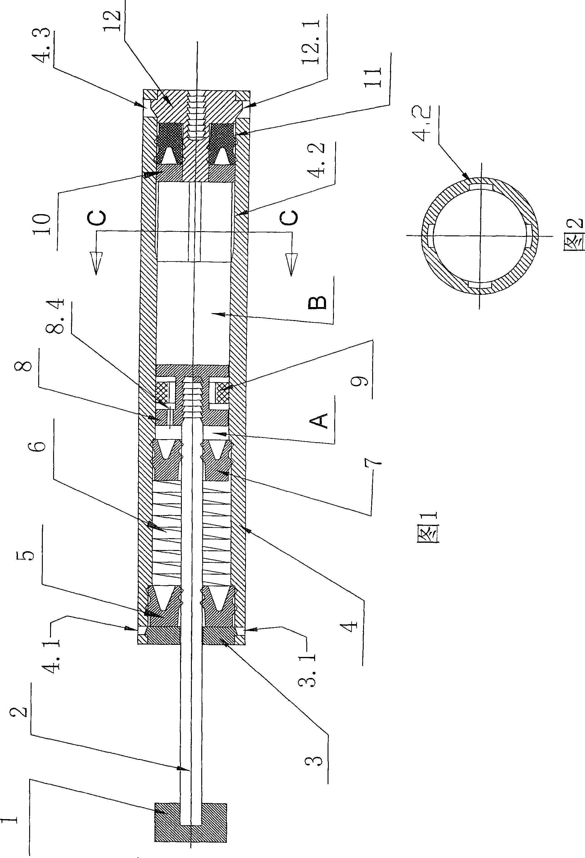
[0059] Referring to Fig. 1, the present invention relates to a hydraulic damper with excellent sealing performance. The damper is specifically a closed cylinder 4, and the inner chamber of the cylinder 4 is divided into a first cylinder 4 by a piston 8 that can slide in the cylinder 4. Studio A and a second studio B. The first working chamber A and the second working chamber B are separated by the piston 8 and filled with a hydraulic fluid.

[0060] The damper has a piston, a piston rod 2 which is led out of a cylinder 4 through a first working chamber A in a sealing manner, the end of which is connected to the front connecting piece 1 .

[0061] A guide sleeve 3, a front leather cup 5, a spring 6 and a middle leather cup 7 are closely arranged in the cylinder body 4 between the piston 8 and the leading end of the piston rod. The guide sleeve 3 is arranged close to the leading end of the piston rod. , The middle cup 7 is set close to the piston 8.

[0062]At least two protru...

Embodiment 2

[0068] Referring to Fig. 7, the difference between the present embodiment and the first embodiment is that the spring of the elastic element 6 is replaced by a sponge, and the center of the sponge is provided with a support 13 sleeved on the shaft to ensure that the sponge is not compressed in the axial direction. Leather cup 7 in example one is used retaining ring 7 instead, and retaining ring 7 does not need sealing with cylinder body cylinder wall.


PUM


Abstract

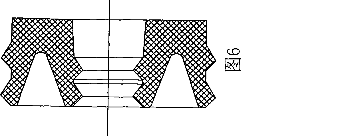
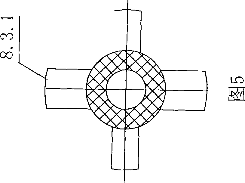
The invention relates to a hydraulic damper with excellent tightness, which is provided with a cylinder body (4), a piston (8), a piston rod (2), a guiding sleeve(3), a front rubber cup(5), an elastic element (6), a middle rubber cup (7)or a fixing ring(7), a blanking element(12), a washer (10)and a rear rubber cup (11), wherein the periphery of the guiding sleeve(3) is provided with a clamping block (3.1), the cylinder body (4) is provided with a bayonet (4.1) matched with the clamping block (3.1), the periphery of the blanking element(12) is provided with a clamping block (12.1), and a bayonet (4.3) is arranged on the cylinder body (4), and the cylinder wall of the hydraulic damper cylinder body (4) is provided with a liquid releasing groove (4.2); the piston (8) is arranged to be a transverse I-shaped contoured structure, and comprises two piston rings(8.1 and 8.3) in the front and at the back and a piston column (8.2) in the middle; the piston column in the middle is sleeved with a floating ring (9), wherein the front piston ring wall is provided with a damping hole (8.4); and the front rubber cup (5), the middle rubber cup (7) and the rear rubber cup (11) of the hydraulic damper are arranged to be internal and external double-lip structures. The hydraulic damper has simple assembling and firm connection among the guiding sleeve and the blanking element with the cylinder wall of the cylinder body, the piston rod can position accurately, and the damping effect and the tightness are good.

Description

(1) Technical field [0001] The invention relates to a damper. It is suitable for all kinds of drawer rails, sliding doors, pull baskets and other parts that need cushioning. The utility model belongs to the technical field of sealed hydraulic pneumatic metal hardware. (2) Background technology [0002] Before the present invention was made, the traditional hydraulic damper had a closed cylinder, and the cylinder chamber was divided into a first working chamber and a second working chamber by a piston that could slide in the cylinder. A working chamber and a second working chamber are filled with a hydraulic fluid, the damper has a piston and a piston rod, the piston rod is guided out of one end of the cylinder through the first working chamber in a sealing manner, the piston and A guide sleeve, a front cup, a fixed ring, and an elastic element are closely arranged in the cylinder between the piston rod outlets, and the guide sleeve is arranged close to the piston rod outle...

Claims


Application Information

Patent Timeline
Patent Type & Authority Applications(China)
IPC IPC(8): F16F9/19F16F9/36F16F9/34F16F9/32
Inventor 卫德义张晓娟王西平
Owner JIANGYIN HUAHONG QIANGSHUN TECH
Why Eureka
Eureka Blog
Learn More