Thread moulding screw

一种攻螺纹、螺钉的技术,应用在攻螺纹的螺钉领域

Active Publication Date: 2009-05-06
HILTI AG
View PDF1 Cites 2 Cited by
  • Summary
  • Abstract
  • Description
  • Claims
  • Application Information

AI Technical Summary

Problems solved by technology

[0005] The known solution has the disadvantage that all blade pins protrude by the same amount from the projected plane of the thread cross section

Method used


Image

  • Thread moulding screw
  • Thread moulding screw
  • Thread moulding screw

Examples


Embodiment Construction

[0021] In principle, identical parts are provided with the same reference numerals in the figures.

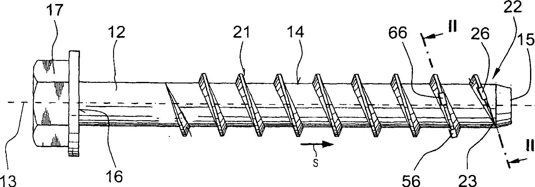
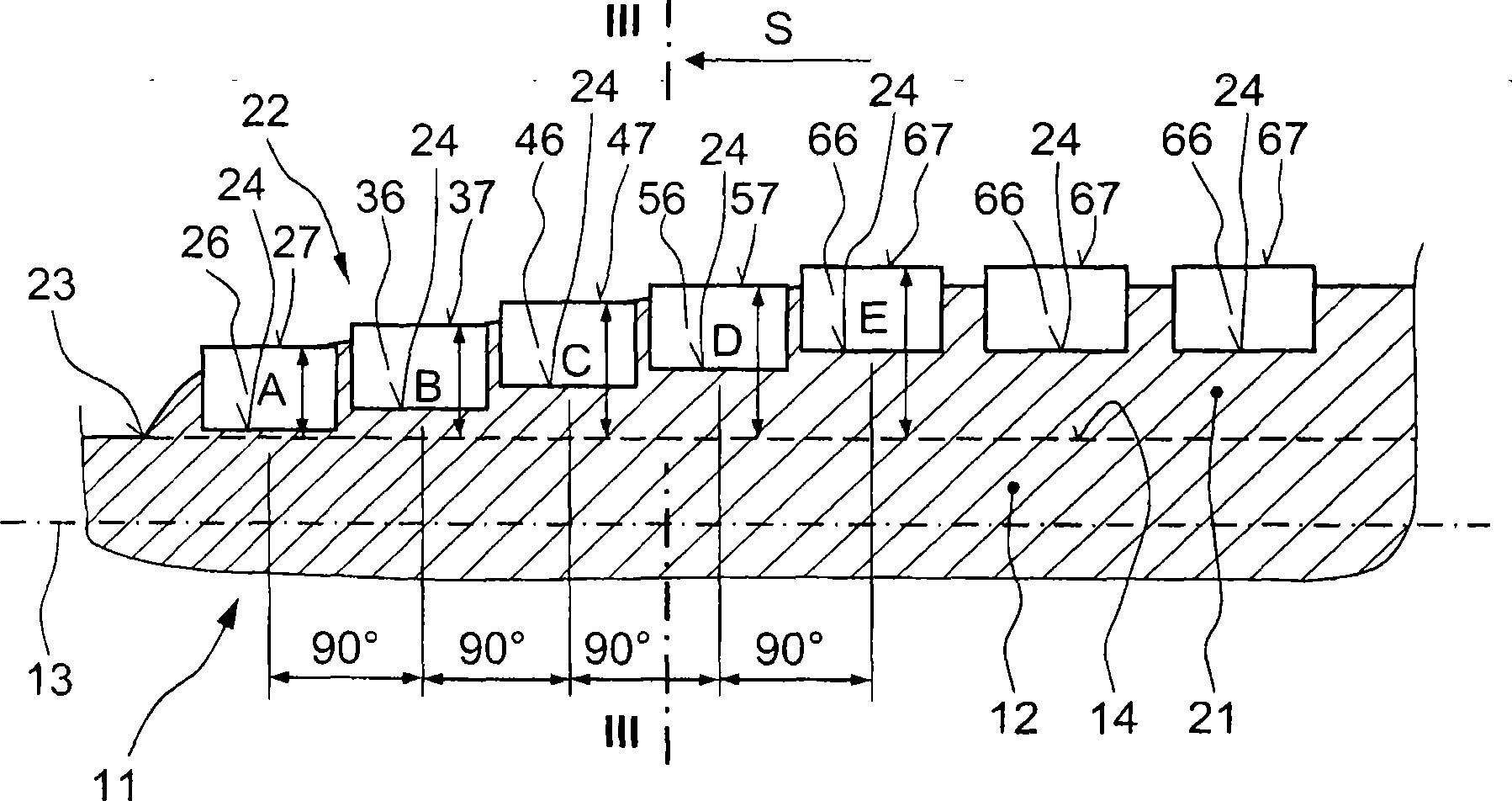
[0022] exist figure 1 and 2 The tapped screw 11 shown in has a shank 12 with which a thread 21 integrally extends from a free end 15 of the shank over at least part of its length. The shank 12 extends along the longitudinal axis 13 of the screw 11 and has a radial shank outer side 14 . At the other end 16 opposite the free end 15, a hexagonal screw head is arranged as the rotationally active element 17. Arrow S in the figure correspondingly indicates the screwing direction of the screw 11 .

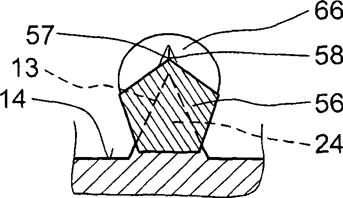
[0023] The thread 21 has cutting bodies 26 , 36 , 46 , 56 , 66 made of a harder material than the thread 21 in a radially outwardly opening recess 24 . The radially outer contours 27 , 37 , 47 , 57 , 67 of the cutting bodies 26 , 36 , 46 , 56 , 66 protrude at least partially beyond the thread 21 . The height of the thread 21 relative to the outside 14 of the shank decreases continuous...


PUM


Abstract

A thread-tapping screw (11) has a thread (21) extending, starting from the screw shaft free end (15), at least along a portion of the shaft length and a height of which constantly decreasing toward the free end (15) of the shaft (12), and a plurality of cutting bodies (26, 36, 46, 56, 66) formed of a material having a greater hardness than hardness of the thread (21), located in recesses (24 ) formed in the thread (21) and opening radially outwardly and having, respectively, a radial outer profile (27, 37, 47, 57, 67) projecting, at lea st partially, beyond the thread and a height (A, B, C, D, E) of which decreases toward the free end (15) of the shaft (12) stepwise.

Description

technical field [0001] The invention relates to a threaded screw having a shank, from a free end of which a thread extends over at least part of its length, the thread having a hardness greater than that of the thread at least partly in a radially outward opening A cutting body made of a hard material, wherein the radially outer contour of the cutting body protrudes at least partially beyond the thread. Background technique [0002] This screw is screwed directly into the drilled hole that has been processed on the base, at this time the thread of the screw taps or cuts out the corresponding thread or undercut on the base. [0003] For field applications, the screws, such as concrete screws, are preferably made of corrosion-resistant materials, such as corrosion-resistant steel. However, the hardness of this material is often not sufficient for tapping on a mineral basis, so that the thread of the screw wears out when screwed in. In the case of corrosion-resistant material...

Claims


Application Information

Patent Timeline
Patent Type & Authority Applications(China)
IPC IPC(8): F16B25/00
CPCF16B25/00F16B25/0026F16B25/0052
Inventor P·格斯塔施B·奥米勒
Owner HILTI AG
Why Eureka
Try Eureka