
Power transmission chain made from metal

An energy guide chain, metal technology, applied in the field of energy guide chain, can solve the problems of environmental impact and limitation of the application of plastic energy guide chain

Active Publication Date: 2009-04-29
椿本缆线牵引有限公司
View PDF8 Cites 3 Cited by
  • Summary
  • Abstract
  • Description
  • Claims
  • Application Information

AI Technical Summary

Problems solved by technology

In addition, the application of plastic energy guide chains may be limited by environmental influences

Method used


Image

  • Power transmission chain made from metal
  • Power transmission chain made from metal
  • Power transmission chain made from metal

Examples


Embodiment Construction

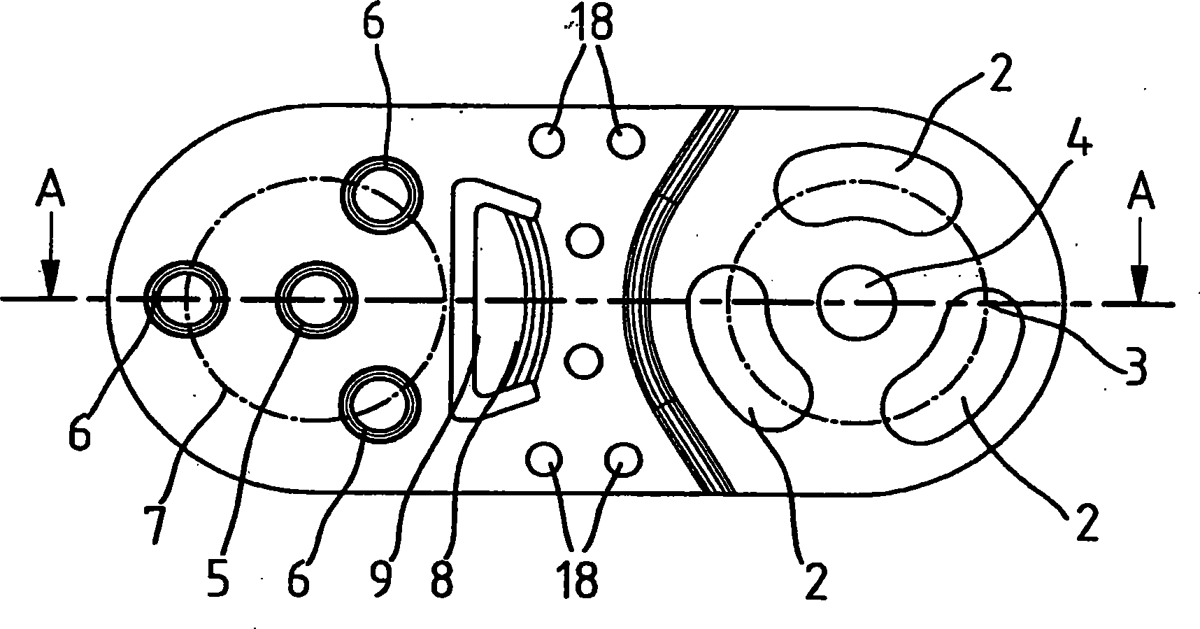
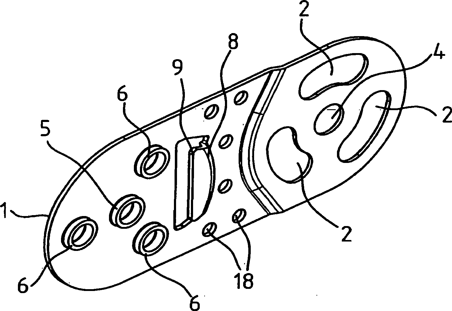
[0044] exist figure 1The chain plate for the energy-conducting chain link is shown in front view in . The link plate 1 consists of metal and has a first end region and a second end region. In the exemplary embodiment shown, the first end region has three through openings 2 . The through-holes 2 are designed as circular arcs, and they lie on a common imaginary circumference 3 . The through opening 2 surrounds a substantially circular through opening 4 which is substantially concentric to the imaginary circle 3 .

[0045] A plurality of elements 5 , 6 corresponding in number to the number of through-holes are formed on the opposite end regions, and these elements are inserted at least partially into corresponding through-holes of the other link plate when forming the energy-conducting chain. The element 5 is arranged centrally so that it can form, with the through-opening 4 , an articulated connection between two adjacent link plates. Elements 6 are arranged on an imaginary ...


PUM


Abstract

For the construction of an energy drag chain a design of a metal bracket is proposed, in which the bracket incorporates a first end-region and a second end-region, the first end-region having at least two cut-outs (2, 4). The second end-region of the metal bracket incorporates a number of elements (5, 6) corresponding to the number of cut-outs (2, 4), which elements when forming an energy drag chain at least partially extend into the respective cut-out of another bracket, whereby the elements (5, 6), shaped by a reforming process, in particular collar forming, protrude from the plane of the bracket.

Description

technical field [0001] The subject matter of the invention relates to a metal chain plate of a chain link of an energy-conducting chain, a chain link of an energy-conducting chain and an energy-conducting chain. Background technique [0002] In order to guide lines, hoses, tubes etc. between a fixed connection point and a movable connection point, so-called power chains are used. Pipelines are used to conduct or guide energy, service media, etc. to the site of use. The movable energy consumer can be, for example, a saddle of a machine tool. It is known that energy guide chains can be made of plastic. Such plastic energy guide chains are limited in their fields of application. [0003] This restriction can be caused by the leading lines, hoses or the like. In certain applications, the weight of the pipeline is so large that it exceeds the carrying capacity of the plastic energy guide chain. Furthermore, the application of plastic energy guide chains may be limited by env...

Claims


Application Information

Patent Timeline
Patent Type & Authority Applications(China)
IPC IPC(8): F16G13/16H02G11/00
CPCH02G11/006F16G13/16Y10T29/4984H02G11/00
Inventor G·舒伯尔C·黑普纳
Owner 椿本缆线牵引有限公司
Learn More