Relative rotation measuring and rotating positioning system and method for small gapping place

A relative rotation and positioning system technology, applied in the field of precision measurement, can solve the problems of large accuracy errors and other problems, and achieve the effects of easy debugging, strong process adaptability, and strong adaptability

Inactive Publication Date: 2011-06-01
XI AN JIAOTONG UNIV
View PDF0 Cites 0 Cited by
  • Summary
  • Abstract
  • Description
  • Claims
  • Application Information

AI Technical Summary

Problems solved by technology

[0005] Aiming at the problem of large errors in rotation, positioning and alignment accuracy in contact or proximity lithography, the present invention proposes a method for high-precision measurement of direction identification and positioning with a relatively small amount of rotation between two planes

Method used


Image

  • Relative rotation measuring and rotating positioning system and method for small gapping place
  • Relative rotation measuring and rotating positioning system and method for small gapping place
  • Relative rotation measuring and rotating positioning system and method for small gapping place

Examples


Embodiment Construction

[0034] Below in conjunction with accompanying drawing, the present invention will be further described:

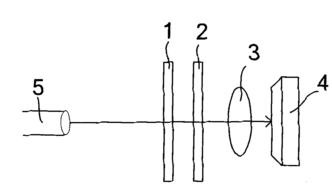
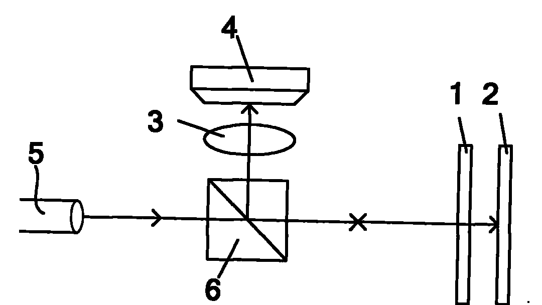
[0035] The present invention can adopt figure 1 reflective measurement system as shown or as figure 2 The transmission measurement system shown. The measurement system includes plane 1 and plane 2 that need to be rotated and positioned, imaging lens group 3, charge-coupled device image sensor CCD4 and light source 5, and a spectroscope 6 for reflective measurement systems. The magnification of the lens group 3 in the optical system is selected according to the size of the grating and the size of the image sensor CCD 4 of the charge-coupled device, and ensures that the image sensor CCD 4 of the charge-coupled device can collect more than 40 fringes. Plane 1 and Plane 2 that need to be positioned contain grating marks for zero point positioning and rotation measurement, such as image 3 and Figure 4 As shown, the pitches of grating 7 and grating 8 on plane 1 are P1 and...


PUM


Abstract

The invention discloses a system and a method for the high-precision measurement direction sensing and rotary positioning of relative micro-rotation between two planes. Two gratings are arranged on the two planes to form two groups of measurement grating pairs. When the amount of relative rotation between the two planes is zero, grid lines of all gratings are in the same direction. Two groups of measurement grating pairs are opposite in the size relation of grating size but identical in period ratio. The number of fringes acquired by a measurement system is not less than 40. The method for measurement direction sensing and rotary positioning comprises the following steps of adopting the dimensions of fringe inclination angles obtained in the horizontal-vertical direction and two diagonal directions to obtain the directions of the fringe inclination angles. When two groups of interference fringes are identical in direction, rotary zero-point positioning is realized between the two planes, and when two groups of interference fringes are different in direction, relative rotation amount exists between the two planes.

Description

technical field [0001] The invention belongs to the field of precision measurement in micro-manufacturing, in particular to a system and method for relative rotation measurement and rotation positioning between small gap planes based on grating interference theory. Background technique [0002] In integrated circuit manufacturing, accuracy, resolution and production capacity are the basic indicators to measure any lithography process. Due to the complex graphics of VLSI and ULSI, the requirements for subsequent graphics and device processing are also different. Likewise, very high stitching and registration accuracy is required during fabrication. As one of the most powerful candidate technologies for sub-0.1 micron lithography in the future, imprint lithography applies the traditional mold replica principle to the field of micro-manufacturing. It is a low-cost integrated circuit manufacturing technology, but in multilayer imprinting In step-by-step imprinting, the alignmen...

Claims


Application Information

Patent Timeline
Patent Type & Authority Patents(China)
IPC IPC(8): G01B11/26G03F7/20
Inventor 刘红忠丁玉成邵金友王莉肖本好尹磊史永胜蒋维涛
Owner XI AN JIAOTONG UNIV
Why Eureka
Try Eureka