Structure, forming method of structure, structure forming device, structure color, diffraction light reading method, and truth/false discriminating method

A structure and structural color technology, applied in diffraction gratings, optics, optical components, etc., can solve the problems of difficult structural color and few practical examples, and achieve the effect of avoiding cost increase and simple material composition.

Inactive Publication Date: 2009-04-22
TOYO SEIKAN KAISHA LTD
View PDF2 Cites 11 Cited by
  • Summary
  • Abstract
  • Description
  • Claims
  • Application Information

AI Technical Summary

Problems solved by technology

[0004] It is difficult to realize such structural color artificially, and there are not many practical examples in industry

Method used


Image

  • Structure, forming method of structure, structure forming device, structure color, diffraction light reading method, and truth/false discriminating method
  • Structure, forming method of structure, structure forming device, structure color, diffraction light reading method, and truth/false discriminating method
  • Structure, forming method of structure, structure forming device, structure color, diffraction light reading method, and truth/false discriminating method

Examples


Embodiment 1

[0277] The Q-switched pulsed YAG laser beam is split into multiple beams by a transmissive diffractive optical element. Each beam was passed through a synthetic quartz plano-convex lens with a focal length of 200 mm placed at a distance of 200 mm from the diffractive optical element. At the position where the passing beam is focused, the mask shields and interferes with the unnecessary beam, and allows only the required beam to pass. The passing beam was condensed by a synthetic quartz plano-convex lens with a focal length of 100 mm, and the beams were crossed and interfered. A 2-axis extended PET sheet was irradiated in the region of interference. First, irradiation was performed at a laser wavelength of 355 nm (transmittance of the PET plate: 83%).

[0278] Next, irradiation was performed by switching the wavelength to 266 nm (the transmittance: 0.3%). The 2D grating period of the diffractive optical element is 6 μm. Specifications of pulsed YAG laser: pulse width is 5ns...

Embodiment 2

[0286] As in Example 1, only a laser with a wavelength of 266 nm was used to irradiate the biaxially stretched PET plate. Structural colors of the formed 2-dimensional structures were observed.

[0287] If ester oil (CAS-Nr: 195371-10-9) with a refractive index of 1.518 (CAS-Nr: 195371-10-9), which is similar to the refractive index of stretched PET sheets of 1.64, is applied to the periodic structure, the structural color is not observed, but the original transparent stretch is observed. PET board.

[0288] (comparison with comparative example)

[0289] Second, refer to Figure 20 ~ Figure 22 A comparison between the structured body of the present embodiment and the comparative example will be described.

[0290] (Comparison of Voids and Cavities)

[0291] The technique of forming a plurality of microscopic cavities inside a substance to develop color is JP2004-359344 A "Plastic Packaging and Decorating Method" (hereinafter referred to as Comparative Example 1).


PUM


Abstract

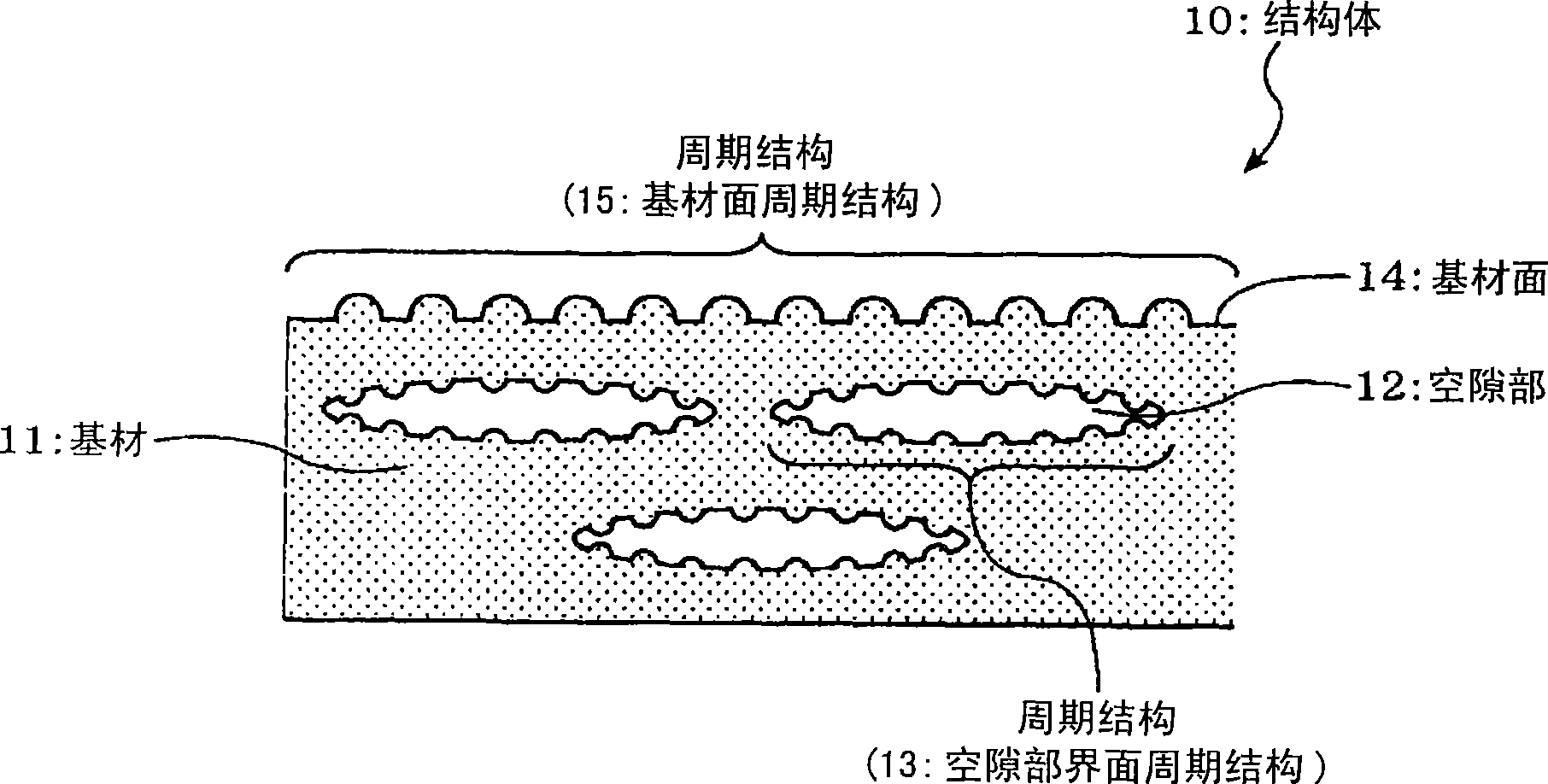
It is possible to make decorative a material excellent in recycling feature while satisfying a requirement for industrially putting a structure color to practical use. It is also possible to easily verify whether an object is genuine or nor, and re-use by separating a hologram seal or the like is made impossible. A cavity (12) having at the interface a cyclic structure (13) causing optical diffraction is formed inside a substrate (11), and a cyclic structure (15) causing optical diffraction is formed on part or the whole of the surface of the substrate (11). The cavity interface cyclic structure (13) and the substrate surface cyclic structure (15) have regular arrangements that develop a structure color. When a functional material is allowed to contact the substrate surface cyclic structure (15), structure color development by the substrate surface cyclic structure (15) is prevented to make it possible to read a structure color developed by the cavity interface cyclic structure (13).

Description

technical field [0001] The present invention relates to a structure having light control performance utilizing optical phenomena such as diffraction and interference, a method for forming the structure, a device for forming the structure, and reading of the structural color and / or diffracted light embodied in the structure. A method for extracting, and a method for judging authenticity using the structure, particularly relating to the ability to prevent illegal reuse and to judge authenticity by forming voids inside the substance and forming periodic structures on the interface of the voids to reflect structural color. The method is easy to form a structure with anti-counterfeit effect marks, the formation method of the structure, the structure formation device, the structural color and / or diffraction light reading method, and the authenticity judgment method. Background technique [0002] In recent years, chemical color development using dye substances has been less and les...

Claims


Application Information

Patent Timeline
Patent Type & Authority Applications(China)
IPC IPC(8): G02B5/18G02B1/02
Inventor 汤浅义之竹之内健
Owner TOYO SEIKAN KAISHA LTD
Why Eureka
Try Eureka