Full hydraulic furnace pounding machine

A furnace pounding machine, full hydraulic technology, applied in the direction of furnaces, mechanical equipment, furnace components, etc., can solve problems such as easy-wearing rollers, deformation of rotating plates, etc., to achieve the effect of protection against deformation, stable performance, and full of creativity

Inactive Publication Date: 2009-04-15
单世纲
View PDF0 Cites 6 Cited by
  • Summary
  • Abstract
  • Description
  • Claims
  • Application Information

AI Technical Summary

Problems solved by technology

[0007] The purpose of the present invention is to provide a fully hydraulic furnace with stable performance and scientific structure in view of the problem that the rotating plate is deformed and the rollers are easily worn due to the unbalanced force of the furnace currently used.

Method used


Image

  • Full hydraulic furnace pounding machine

Examples


Embodiment Construction

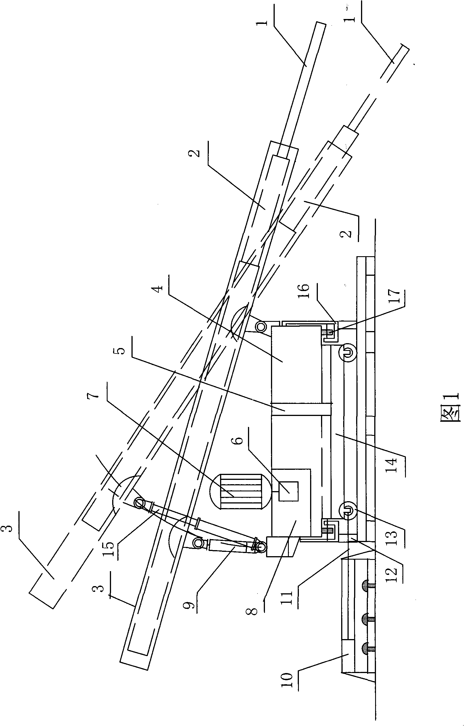
[0027] The full hydraulic furnace stamping machine includes a carrying mechanism, a furnace stamping mechanism, a power mechanism, and a slewing beam; the carrying mechanism includes a base 14 and a walking cylinder 10; wheels 13 are arranged under the base 14, and columns 12 are arranged under the four corners of the base 14. The wheel bracket at the rear end of the base 14 is tightly connected with the movable connecting rod 11 at the front part of the traveling oil cylinder 10, and the traveling oil cylinder 10 is fixed on the foundation.

[0028] The furnace pounding mechanism includes an outer arm 3, an inner arm 2, a pounding head 1, and a luffing oil cylinder 9; an inner arm 2 is arranged inside the outer arm 3, and the inner arm 2 and the outer arm 3 are dynamically matched and connected by hydraulic pressure. The front end of the arm 2 is provided with a tamping head 1, the tamping head 1 is fixedly connected with the inner arm 2, the rear part of the outer arm 3 is hi...


PUM


Abstract

A full-hydraulic stoking machine comprises a conveying mechanism, a stoking mechanism and a rotary beam. Wheels are arranged under a seat; plinths are arranged on the lower parts of four angles of the seat; a wheel bracket at the back end of the seat is fixedly connected with a movable linkage-rod of a translation cylinder; an inner arm is movably connected with an outer arm in a matching way through the hydraulic manner to do telescopic movement; a stoking head is arranged at the front end of the inner arm and the back part of the outer arm is articulated with the movable linkage-rod of an amplitude cylinder; the rotary beam is arranged on the seat and rotationally connected with the seat through a central shaft. An L-shaped rotary support frame is respectively arranged at both the front end and the back end of the rotary beam; the bottom surface of the L-shaped rotary support frame is buckled with the lower surface of the arc side of the seat; and a tensile roller is arranged between the lower surface of the seat edge and the L-shaped rotary support frame. The design of the full-hydraulic stoking machine is scientific and reasonable; the structure is compact and tight; the materials can be saved; the manufacturing cost is low; the function is complete; the operation is easy; the efficiency is high; the manufacturing process is simple; the performance is stable; and the practicability is higher. The full-hydraulic stoking machine is applicable to the metallurgy industry.

Description

technical field [0001] The invention relates to a furnace stamping machine used in the metallurgical industry, in particular to a fully hydraulic furnace stamping machine. Background technique [0002] In the smelting of ferroalloys, the surface of the charge is prone to compaction, which greatly affects the gas permeability of the charge, which also affects the efficiency and quality of smelting, and also increases energy consumption. Therefore, it is necessary to use the furnace from time to time. The tamping head of the machine performs operations such as tamping, turning, pricking, and loosening on the hardened surface to improve the efficiency of smelting. [0003] Although the furnace smelters currently in use are of various styles, they can generally be classified into two types: mechanical chain type and hydraulic type, but in actual use, it is found that they have problems and defects in different degrees. [0004] 1. The structure of the mechanical ramming machine...

Claims


Application Information

Patent Timeline
IPC IPC(8): F27D3/00F27D23/00F27D99/00
Inventor 单世纲
Owner 单世纲
Why Eureka
Try Eureka