Processing system for process object and thermal processing method for process object

A heat treatment method and the technology of the object to be processed are applied in thin material processing, transportation and packaging, semiconductor/solid-state device manufacturing, etc., which can solve the problems of production reduction and achieve the effect of preventing thermal damage and increasing production

Inactive Publication Date: 2009-04-08
TOKYO ELECTRON LTD
View PDF6 Cites 7 Cited by
  • Summary
  • Abstract
  • Description
  • Claims
  • Application Information

AI Technical Summary

Problems solved by technology

[0015] However, in this case, the retreat time for retracting the above-mentioned transfer arm mechanism is generally a long time from the start of unloading to the completion of unloading and the position where the upper part of the object transfer area is sufficiently cooled by the ambient temperature.
Therefore, for example, although the upper part of the atmosphere temperature in the target object transfer area is lowered to a safe temperature for the above-mentioned members constituting the transfer arm mechanism, there is a state in which the transfer operation of the wafer remains prohibited, thus causing production failure. volume reduction problem

Method used


Image

  • Processing system for process object and thermal processing method for process object
  • Processing system for process object and thermal processing method for process object
  • Processing system for process object and thermal processing method for process object

Examples


Embodiment Construction

[0043] Hereinafter, a preferred example of the processing system for an object to be processed and the method for heat treating an object to be processed according to the present invention will be described in detail with reference to the drawings.

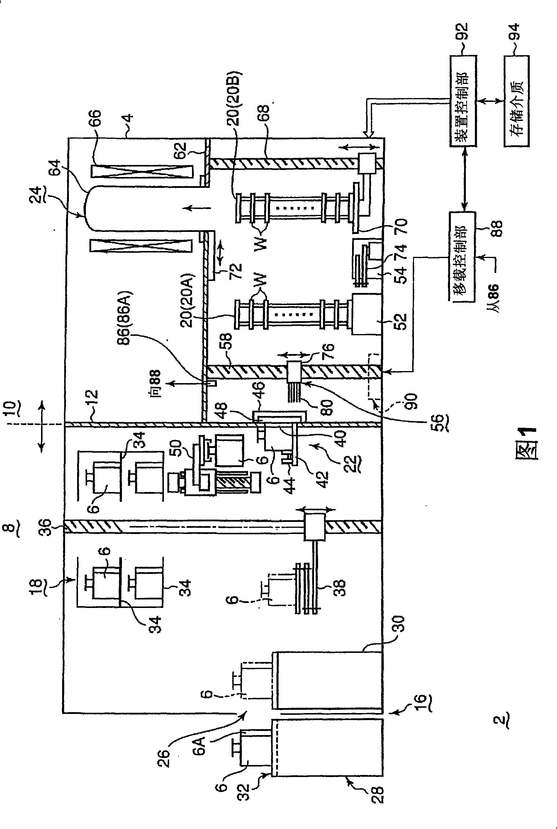
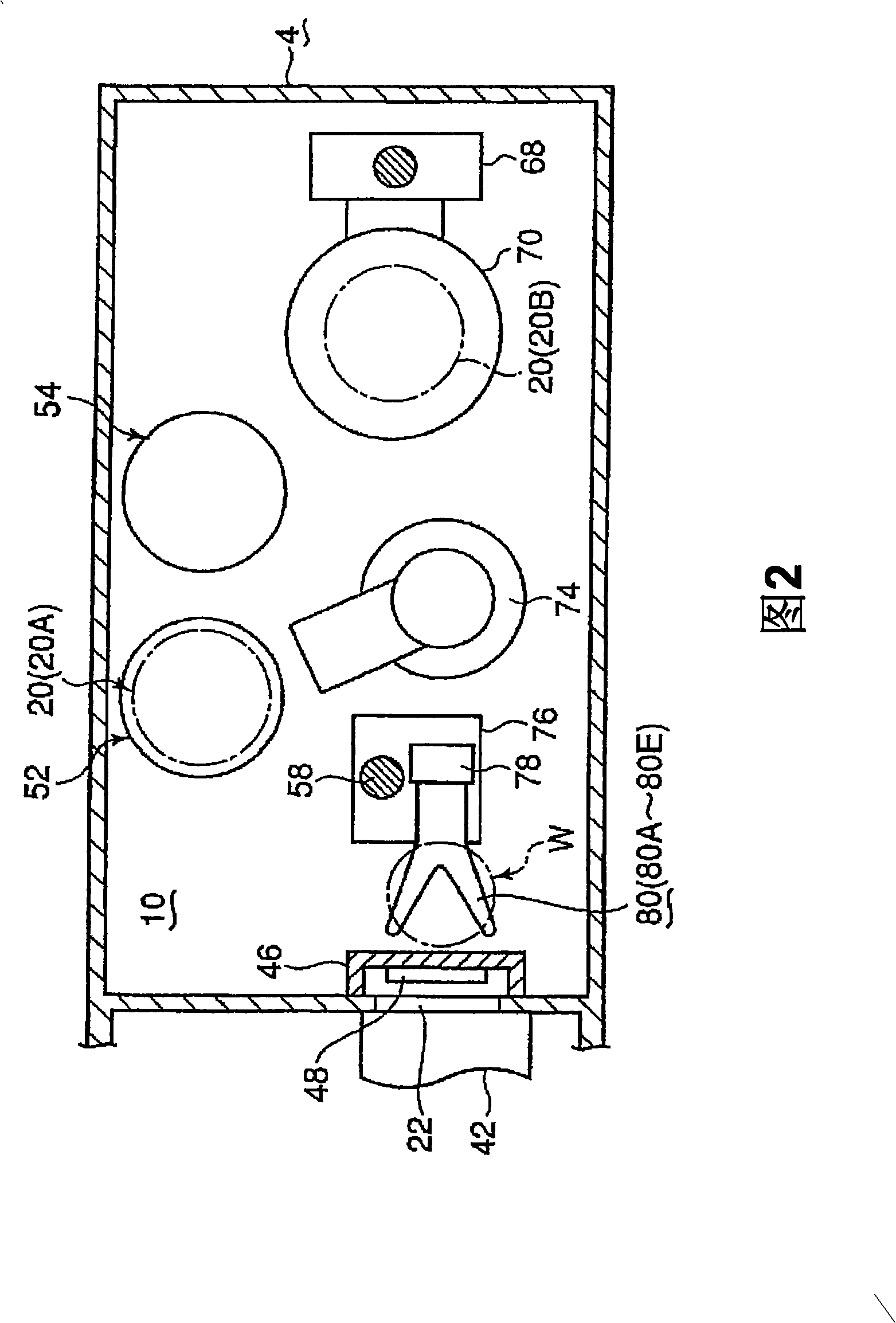
[0044] Fig. 1 is a schematic configuration diagram showing an example of the processing system of the object to be processed according to the present invention, Fig. 2 is a plan view showing an example of the arrangement position of each constituent member in the object transfer region, and Fig. 3 is a schematic diagram showing A diagram of an example of a transfer arm mechanism for an object to be processed.

[0045] First, as shown in FIG. 1 and FIG. 2, the processing system 2 of the object to be processed is surrounded by a frame body 4, which functions as a partition wall as a whole, and is made of, for example, stainless steel, and its interior is divided into: There are two parts: a storage box transfer area 8 for transferri...


PUM


Abstract

The present invention provides a processing system for a process object capable of preventing a transport arm mechanism from being thermally damaged, so as to effectively perform a transport operation of the process object. A processing system 2, which takes out a process object W from a storage box 6 for process object, and thermally process the process object, includes: a vertical processing unit 24; a process-object transport area 10 disposed below the processing unit; a plurality of process-object boats 20 configured to hold the process objects; a boat elevating means 68 configured to vertically move the process-object boat 20; a boat table for transport 52, on which the process-object boat can be placed; and a transport arm mechanism configured to transport the process objects between the storage box 6 and the process-object boat 20 placed on the boat table for transport 52. The transport arm mechanism 56 is vertically moved by an arm elevating means 58. A temperature measuring means 86 is disposed in an upper part in the process-object transport area. The transport arm mechanism 58 and the arm elevating means 58 are controlled by a transport control part 88 based on a measured value of the temperature measuring means 86, so that a transport operation of the transport arm mechanism is controlled.

Description

[0001] technology area [0002] The present invention relates to a processing system for transferring an object to be processed from a storage box containing a semiconductor wafer or the like to an object carrier in an object transfer area for heat treatment of the object to be processed and an object to be processed Body heat treatment method. Background technique [0003] Generally, in order to manufacture semiconductor integrated circuits such as ICs and LSIs, various film formation processes, oxidation diffusion processes, and etching processes are repeatedly performed on semiconductor wafers. When performing various processes, semiconductor wafers need to be transported between corresponding devices. In this case, a plurality of semiconductor wafers, for example, 25 semiconductor wafers are stored and transported in the storage box at a time. As such a storage box, known is: a storage box that is transported in an open state relative to atmospheric treatment like a box, ...

Claims


Application Information

Patent Timeline
Patent Type & Authority Applications(China)
IPC IPC(8): H01L21/00H01L21/677
CPCH01L21/67109H01L21/67248H01L21/67276H01L21/67754H01L21/67766Y10S414/138H01L21/6773Y10S414/14
Inventor 菱谷克幸高桥喜一
Owner TOKYO ELECTRON LTD
Why Eureka
Try Eureka