Air stirring pipe for electroplating production equipment

A technology of air stirring and production equipment, which is applied in the direction of electrolysis process, electrolysis components, mixers, etc., can solve the problems of uneven stirring, weak stirring, non-complementary, etc., and achieve enhanced stirring effect, increased bubbles, and enlarged stirring area Effect

Active Publication Date: 2009-04-08
WUXI XINGYI INTELLIGENT ENVIRONMENT EQUIP CO LTD
View PDF0 Cites 6 Cited by
  • Summary
  • Abstract
  • Description
  • Claims
  • Application Information

AI Technical Summary

Problems solved by technology

Due to the sufficient air volume in the middle of the H-shaped tube, the stirring is strong, and the stirring at both ends is weak, and there are pipe plugs at both ends, so that the air on both sides cannot complement each other, so the stirring is uneven.

Method used


Image

  • Air stirring pipe for electroplating production equipment
  • Air stirring pipe for electroplating production equipment
  • Air stirring pipe for electroplating production equipment

Examples


Embodiment Construction

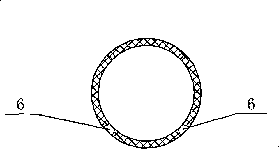
[0012] See Figure 2, Figure 3, Figure 5 , the stirring tube body 2 of the present invention, the stirring tube body 2 is assembled and connected into a "day" shape by the pipe 5 and the elbow 4, the horizontal tube in the middle is connected to the main intake pipe 3, and the air outlet 6 is distributed at the bottom of the stirring tube 2 (see Figure 3), distributed along the airflow direction and the number is getting denser, see Figure 5 . The air outlet hole 6 is a tapered hole with a small inside and a big outside; see Figure 4 , the air outlet holes 6 are staggered; the staggered angle of the adjacent air outlet holes 6 is 120°, 90° or 60° ( Figure 5 90° in the center).


PUM


Abstract

The invention relates to an air stirring pipe used for an electroplating production device. The stirring pipe can not only stir the solution uniformly, but also can save air flow. The stirring pipe comprises a stirring pipe body and is characterized in that the stirring pipe is assembled and connected by a pipe and a bend head into a shape of Chinese character 'ri', a middle crossing pipe is connected with an inlet manifold, and air outlet holes are distributed at the bottom of the stirring pipe outwards along the flowing direction of the air flow, and the amount of the air outlet holes is more and more.

Description

(1) Technical field [0001] The invention relates to a stirring tool used in an electroplating line, in particular to an air stirring tube for electroplating production equipment. (2) Background technology [0002] At present, there are two types of stirring tubes in domestic tanks, one is plastic stirring tubes and the other is metal stirring tubes. The structure of these two stirring tubes is the same, both are H-type. The metal pipe is welded by the pipe and the pipe plug. Due to the sufficient air volume in the middle of the H-shaped tube, the stirring is strong, and the stirring at both ends is weak, and there are pipe plugs at both ends, so that the air on both sides cannot complement each other, so the stirring is uneven. (3) Contents of the invention [0003] In view of the above defects, the present invention provides an air stirring tube used in electroplating production equipment, which can not only stir the solution evenly, but also save gas volume. [0004] I...

Claims


Application Information

Patent Timeline
Patent Type & Authority Applications(China)
IPC IPC(8): C25D21/10B01F13/02B01F33/40
Inventor 匡优新
Owner WUXI XINGYI INTELLIGENT ENVIRONMENT EQUIP CO LTD
Why Eureka
Try Eureka