Eureka AIR delivers breakthrough ideas for toughest innovation challenges, trusted by R&D personnel around the world.

Material feeder of lathe

The technology of a feeding device and a pushing device, which is applied in the field of feeding devices and feeding devices of lathes, can solve the problems of workpiece transportation and cannot be used as a feeding device for lathes, and achieve accurate and stable transportation, simple structure, and stable transportation.

Active Publication Date: 2009-04-08
ZHEJIANG SHUANGZHENG MACHINE TOOL CO LTD
View PDF1 Cites 15 Cited by
  • Summary
  • Abstract
  • Description
  • Claims
  • Application Information

AI Technical Summary

Problems solved by technology

[0004] However, this device is used to transport syringe rubber stoppers, and this patent has no screening device, so this patent cannot realize the delivery of workpieces to the next process according to the set state, so this patent cannot be used as a feeding device for lathes

Method used


Image

  • Material feeder of lathe
  • Material feeder of lathe

Examples


Embodiment 1

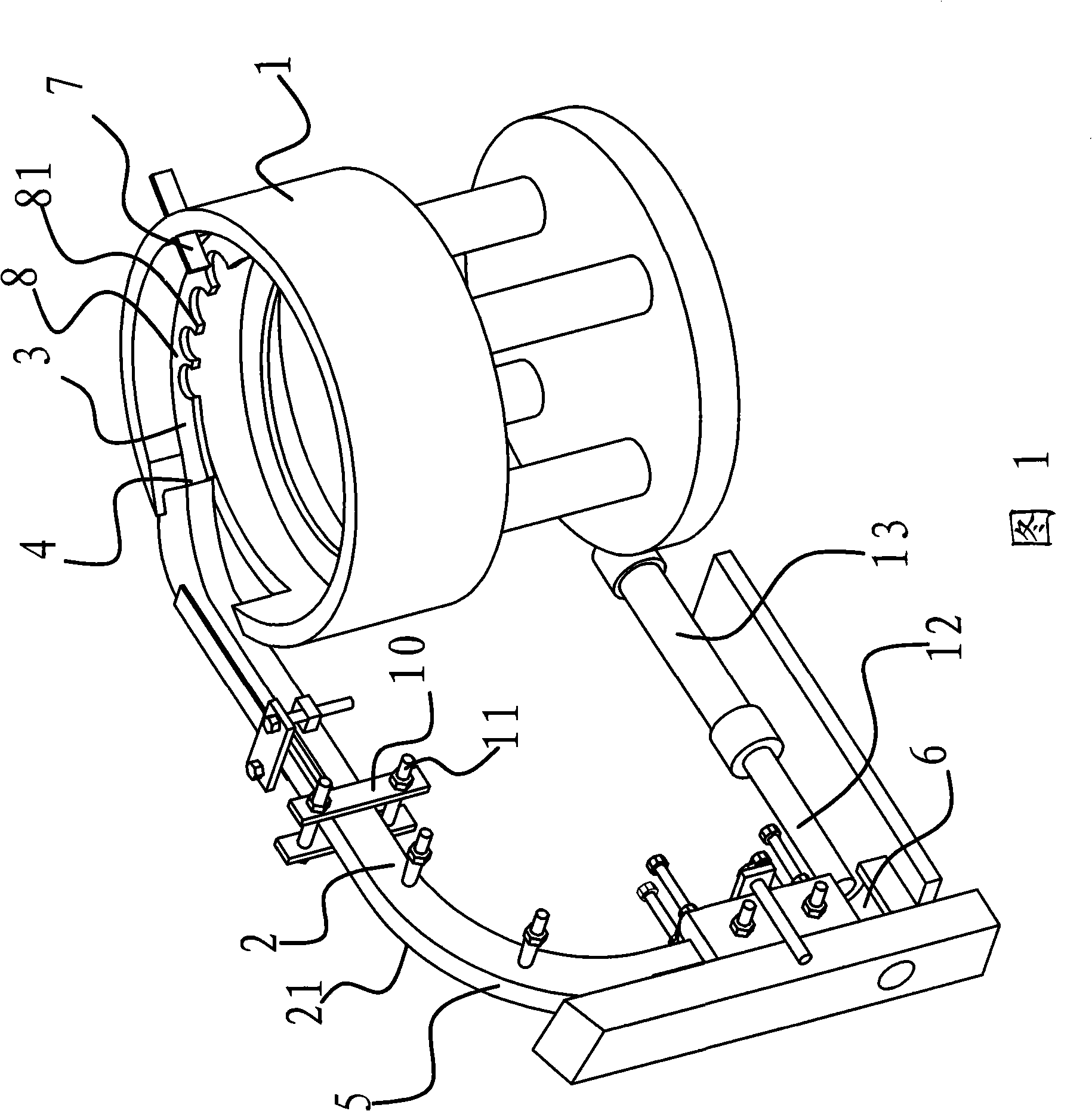
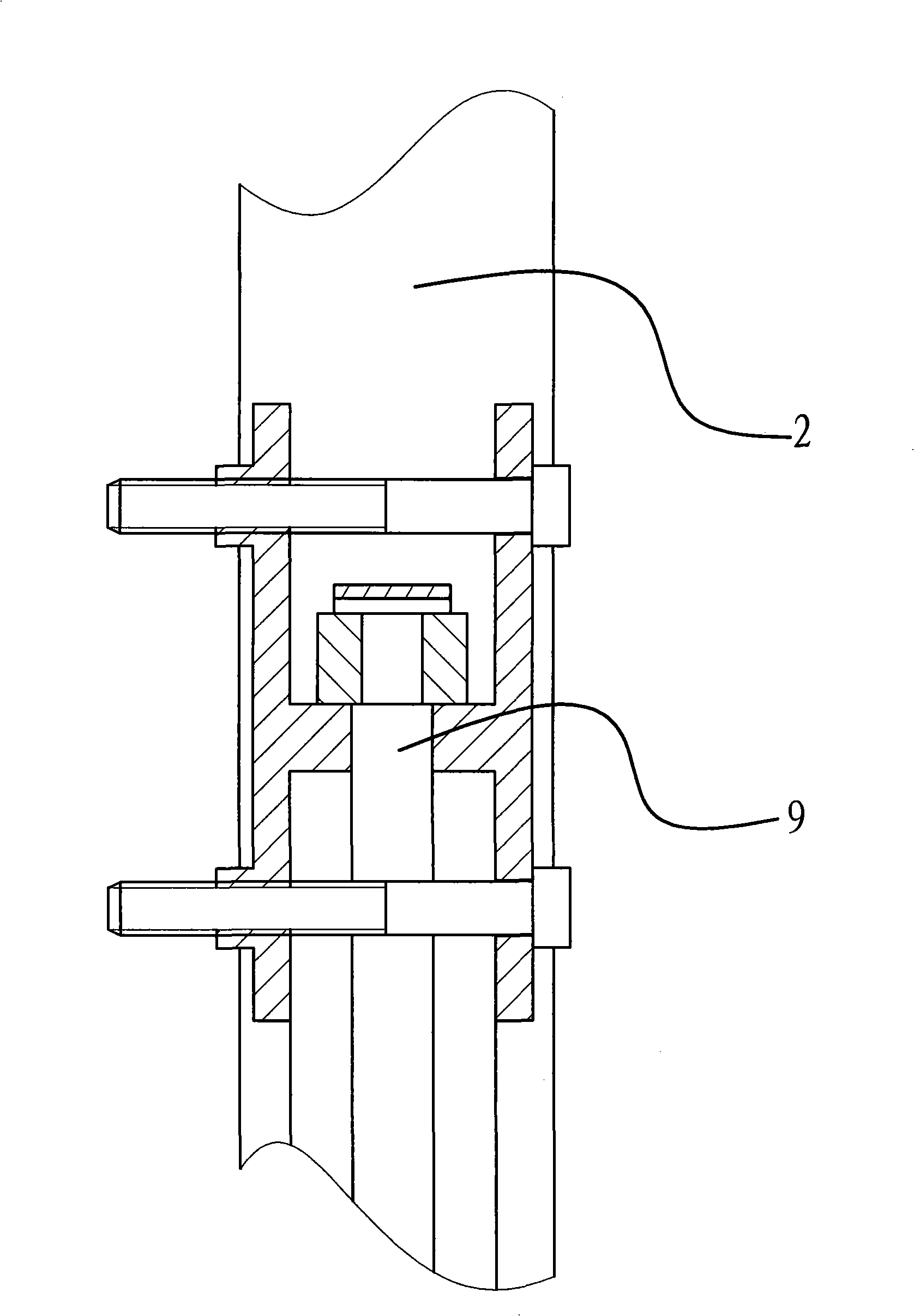
[0025] As shown in the figure: the feeding device of this lathe is used to arrange and transport the workpiece 9 to a processing procedure according to the set arrangement state, including the vibrating hopper 1 and the feeding guide rail 2, on the vibrating hopper 1 There is a spirally rising feeding channel 3, the lowest point of the feeding channel 3 is the feeding port and is located at the bottom of the vibrating hopper 1, the highest point of the feeding channel 3 is the feeding port 4, the feeding port 4 and the feeding end of the feeding guide rail 2 Connected, a screening mechanism is provided on the discharge channel 5 to arrange and output the workpieces 9 according to the set placement state. The discharge end of the feeding guide rail 2 is connected with the top of the feeding tube 6, and the workpieces 9 can fall into the feeding tube. In the pipe 6, a pusher device that can push the workpiece 9 to the next process is provided at the feed pipe 6.

[0026] Screeni...

Embodiment 2

[0030] The content of Embodiment 2 is basically the same as that of Embodiment 1. The difference is that the screening mechanism is a screening guide rail that is located on the feeding channel and communicates with the discharge port. The screening guide rail includes two parallel slide rails. A gap is provided between the rails to allow the workpiece to pass through and move the workpiece along the slide rail. The workpiece mentioned above is columnar and has a large end at one end and a small end at the other end. The small end of the workpiece is smaller than the gap between the two slide rails, and the large end of the workpiece is larger than the gap between the two slide rails. When the workpiece passes through the feeding channel and reaches the screening guide rail, the screening guide rail includes two slide rails arranged in parallel, and a gap is provided between the two slide rails to allow the workpiece to pass through and move the workpiece along the slide rails....


PUM


Abstract

The invention provides a feeding device for a lathe, which belongs to the technical field of machinery. The feeding device for the lathe solves the technical problems that the prior feeding device of the lathe has a complicated structure, unsteady conveying and so on. The feeding device for the lathe comprises a vibratory hopper and a feeding guide rail, wherein the vibratory hopper is provided with a feeding channel which rises spirally, the lowest position of the feeding channel is a feed inlet and is positioned at the bottom of the vibratory hopper, the highest position of the feeding channel is a discharge outlet, the discharge outlet is connected with the feeding end of the feeding guide rail, the feeding channel is provided with a screening mechanism which ensures that workpieces are arranged and output according to the preset arrangement state, the discharge end of the feeding guide rail is communicated with the top of a material placing pipe, workpieces can fall into the material placing pipe, and a pushing device which can push the workpieces to the next working procedure is arranged at the material placing pipe. The feeding device for the lathe has the advantages of simple structure, accurate and steady conveyance, conveyance of more different workpieces and so on.

Description

technical field [0001] The invention belongs to the technical field of machinery and relates to a feeding device, in particular to a feeding device for a lathe. Background technique [0002] At present, many lathes use a vibrating feeder as the feeding device for the workpiece. The vibrating feeder is a kind of equipment that uniformly and continuously transports loose block, granular and powder materials from the vibrating hopper to the receiving position. The device has been widely used in the transportation operations of medicine, building materials, metallurgy, chemical industry, coal and other industries. Vibrating feeders are roughly divided into two types: one is the motor vibrating feeder, and the other is the electromagnetic vibrating feeder. Although the vibration generating devices of these two vibrating feeders are different, their principles are exactly the same, and the structure of the vibrating hopper on the vibrating feeder is basically the same. [0003] ...

Claims


Application Information

Patent Timeline
Patent Type & Authority Applications(China)
IPC IPC(8): B23B13/10B23B15/00
Inventor 陈云法
Owner ZHEJIANG SHUANGZHENG MACHINE TOOL CO LTD
Why Eureka
Eureka Blog
Learn More