High effective absorbent for separating acid gas

An acid gas and absorbent technology, applied in separation methods, through absorption, dispersed particle separation, etc., can solve the problems of reducing the efficiency of absorbent compounds, accelerating equipment corrosion, equipment corrosion, etc., to achieve energy reduction, equipment corrosion reduction, oxidation reduction, etc. and degradation stabilization effect

Inactive Publication Date: 2009-04-01
KOREA ELECTRIC POWER CORP
View PDF3 Cites 8 Cited by
  • Summary
  • Abstract
  • Description
  • Claims
  • Application Information

AI Technical Summary

Problems solved by technology

[0006] Meanwhile, the absorption method using the aforementioned monoethanolamine (hereinafter referred to as "MEA") as an absorbent has a fast reaction rate, but suffers from problems such as large energy consumption in carbon dioxide separation, use of a large amount of absorbent solution, and equipment corrosion due to absorbent solution
Therefore, the loss of alkanolamine absorbent i.e. MEA occurs in the actual process, so that the absorbent needs to be replenished periodically, and the resulting degradation products also accelerate the corrosion of the equipment and reduce the efficiency of the absorbent compound.

Method used


Image

  • High effective absorbent for separating acid gas
  • High effective absorbent for separating acid gas
  • High effective absorbent for separating acid gas

Examples


Embodiment 1

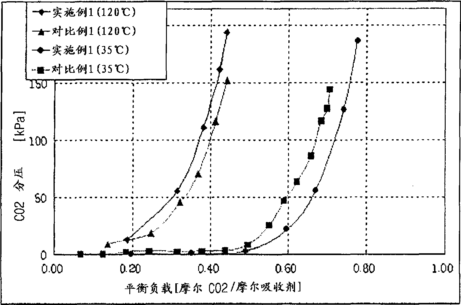
[0051] Put 100mL of 2.00M 1-amino-2-propanol:piperazine (9:1) mixed aqueous solution as an absorbent into a 700mL stainless steel pressure-resistant reactor equipped with a stirrer. Carbon dioxide gas was transferred from the carbon dioxide storage tank to the reactor, and the saturated absorption of carbon dioxide was measured at a carbon dioxide partial pressure ranging from 0.0 kPa to about 150-200 kPa. The reactor and carbon dioxide storage vessel were preheated to the desired temperature in an oven, and the gas-liquid equilibrium curves at 35°C and 120°C were measured, respectively. The result obtained from this is as figure 1 shown.

Embodiment 2

[0053] A glass reaction vessel was immersed in a water bath at 40° C., and then 300 mL of a 2.00 M mixed aqueous solution of 1-amino-2-propanol:piperazine (9:1 ) was charged. Under atmospheric pressure, a gas consisting of 15% carbon dioxide and 85% nitrogen was dispersed at a flow rate of 3.0 L / min through a glass tube and absorbed into the absorbent. The concentration of carbon dioxide in the gas at the outlet of the absorption solution is continuously measured in an infrared carbon dioxide analyzer, from which the absorption rate, absorption capacity and absorption load of carbon dioxide are calculated. At a given time point (approximately 90 minutes), when the absorbent is saturated with carbon dioxide, the reaction vessel is transferred to a water bath pre-warmed to 80°C, and the rate of removal of carbon dioxide from the absorbent is determined. Removal volume and removal rate for 30 minutes. The results thus obtained are given in Table 1 below.

Embodiment 3

[0055] In the same device as in Example 2, a 2.45M 1-amino-2-propanol:piperazine (100:1) mixed aqueous solution was used as an absorbent to measure the removal rate of carbon dioxide and CO in the exhaust gas. 2 Loading on absorbent. The results thus obtained are given in Table 1 below.


PUM


Abstract

Provided is a high-efficiency, low-energy type mixed absorbent for separation of carbon dioxide, which has a rapid reaction rate with carbon dioxide and a high-carbon dioxide absorption capacity and does not require a large amount of energy for regeneration of the absorbent, in conjunction with low risk of absorbent oxidation. The absorbent comprises a mixed aqueous solution of: 100 parts by weight of a compound of Formula 1 having one alcoholic hydroxyl group and one primary amine in the molecular structure with no substituent being on the alpha carbon adjacent to the amine and both of an alkyl substituent and an alcoholic hydroxyl group being on the beta carbon, and 1 to 60 parts by weight of a heterocyclic compound of Formula 2 having at least one amine in the ring: (See formula 1) (See formula 2) wherein R1, R2, R3, R4, R5, and X are as defined in the specification.

Description

technical field [0001] This invention relates to hybrid absorbents for acid gas separation. More particularly, the present invention relates to a hybrid absorbent for carbon dioxide separation, which has a fast reaction rate for reacting with carbon dioxide and a high carbon dioxide absorption capacity, and does not require a large amount of energy for regeneration of the absorbent . Background technique [0002] With the development of industrialization and urbanization in the early nineteenth century, the consumption of fossil fuels such as coal, petroleum, liquefied natural gas (LNG), etc. 2 、CH 4 、H 2 S and COS) concentration increases. Continued industrial development and growth since the mid-twentieth century has resulted in a rapid increase in acid gas concentrations. With the acceleration of global warming due to industrial progress and the increase in the concentration of such acid gases, especially the increase in the level of carbon dioxide in the atmosphere,...

Claims


Application Information

Patent Timeline
Patent Type & Authority Applications(China)
IPC IPC(8): B01D53/62B01D53/78C01B32/50
CPCY02C10/06Y02C10/04Y02P20/50Y02C20/40B01D53/1456B01D53/1475B01D53/1493B01D2252/20484B01D2252/20452B01D2252/20447B01D2252/20442
Inventor 沈在球金俊翰张庆龙柳青杰严熙文许宰实
Owner KOREA ELECTRIC POWER CORP
Why Eureka
Try Eureka