Float valve sealability detection device

A sealing detection and float valve technology, which is applied in the direction of liquid tightness measurement using liquid/vacuum degree, and by measuring the increase and deceleration rate of fluid, can solve the problems of unstable detection pressure, decreased accuracy, and distorted detection results. , to achieve the effect of improving detection speed, fast assembly and disassembly speed, and high precision

Inactive Publication Date: 2009-03-25
黄樟焱
View PDF1 Cites 9 Cited by
  • Summary
  • Abstract
  • Description
  • Claims
  • Application Information

AI Technical Summary

Problems solved by technology

[0007] 2. It is unscientific to use water as a seal detection medium
[0009] The permeability of water is greatly affected by the water temperature and the purity of the water. When the water temperature is low and there are many impurities in the water, the permeability of the water is very poor. At this time, even if there is a penetrating defect on the sealing surface of the float valve, it may Leakage does not occur, which will lead to distortion of detection results and decrease in accuracy
In the actual use of the detection device using this technology, the batch detection results were distorted due to failure to replace the dust-contaminated detection water in time
[0010] 3. The hygienic index of the float valve is not easy to guarantee
Therefore, the float valve tested by the detection device needs to be dried again, otherwise the hygienic index of the float valve cannot be guaranteed, and the drying process needs to increase the cost
[0011] 4. The detection pressure is unstable
The detection pressure is unstable, which will lead to inconsistent test results
[0012] 5. The test results are only qualified or unqualified, and the data cannot be used to quantitatively describe the sealing performance of the float valve

Method used


Image

  • Float valve sealability detection device
  • Float valve sealability detection device
  • Float valve sealability detection device

Examples


Embodiment Construction

[0043] The present invention will be described in detail below in conjunction with specific drawings, but it should be understood that the detailed description herein does not constitute a limitation on the protection scope of the present invention.

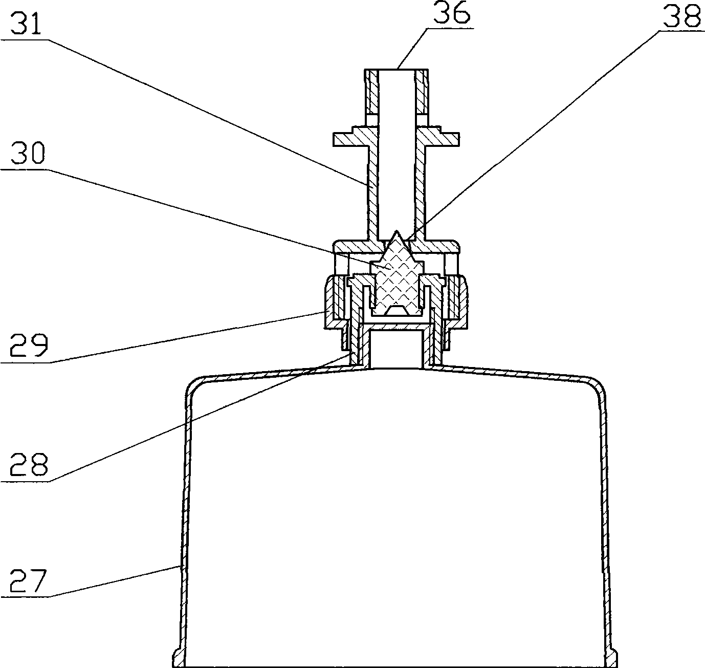
[0044] figure 1 It is a structural schematic diagram of the float valve on the special water purifier for drinking fountains in the prior art. combine figure 1 As shown, the float valve includes a valve body (31), a float (27), a valve disc (28), a tapered gasket (30) and a limit nut (29), and the valve disc (28) is connected to the float (27) through threads. connection, the conical gasket (30) is fixedly assembled on the disc (28), the limit nut (29) is connected with the valve body (31) through threads, and the float (27), valve disc (28) and conical gasket (30) The assembled assembly can slide up and down in the lower cavity of the valve body (31), the stop nut (29) has a positioning and guiding effect on the assembly, an...


PUM


Abstract

The invention discloses a device for detecting tightness of a float valve, which comprises an upper water tank, a lower water tank, a water level display pipe and a water pump for pumping water inside lower water tank to the upper water tank, wherein an ascending pipe, a descending pipe and an overflow pipe are arranged between the upper water tank and the lower water tank; the bottom of the descending pipe is provided with a lower valve for controlling water current in the descending pipe; the bottom of the water level display pipe is communicated to the inlet end close to the lower valve; the top of the water level display pipe is communicated with a high level gas-phase pipe; and the high level gas-phase pipe is communicated with a detecting head. When the float valve is detected, the detecting head is hermetically connected with a water inlet of the float valve, the water level in the upper water tank is constant after the water pump is opened, the pressure generated by the water inside the upper water tank is detecting pressure, and the stable water level inside the water level display pipe reflects sealing performance of the float valve that the lower the stable water level is, the better sealing performance of the float valve is. The device has the advantages of high accuracy and stability of the detecting pressure, no pollution of detecting medium to the float valve, high correctness of the detecting result and describable detecting result with data, and easy operation and quickness during detection.

Description

[0001] Technical field [0002] The invention relates to the technical field of valve sealing performance detection, in particular to a float valve sealing performance detection device, and the float valve is used in a special water purifier for drinking fountains to control the water level in a water bucket of the drinking fountain. Background technique [0003] Water purifiers for water dispensers are generally provided with a float valve to control the water level in the bucket of the water dispenser. When the user takes water from the water dispenser, the float valve opens to allow the water in the water purifier bucket to flow into the bucket of the water dispenser; when the user stops taking water, the float valve continues to open for a period of time until the water level in the bucket rises to the set position , the float valve is closed. After the float valve is closed, if the seal of the float valve is unreliable, the water in the bucket of the water purifier will...

Claims


Application Information

Patent Timeline
Patent Type & Authority Applications(China)
IPC IPC(8): G01M3/28
Inventor 黄樟焱
Owner 黄樟焱
Why Eureka
Try Eureka