
Cable-spun device of ring spinning frame

A spinning frame and cable-type technology, applied in textiles and papermaking, etc., can solve problems such as easy deformation, poor stability, and device position changes, and achieve the effects of no friction loss, reliable operation, and stable rigidity.

Active Publication Date: 2009-03-25
SHANGHAI TEXTILE GRP DETECTION STANDARD CO LTD
View PDF1 Cites 11 Cited by
  • Summary
  • Abstract
  • Description
  • Claims
  • Application Information

AI Technical Summary

Problems solved by technology

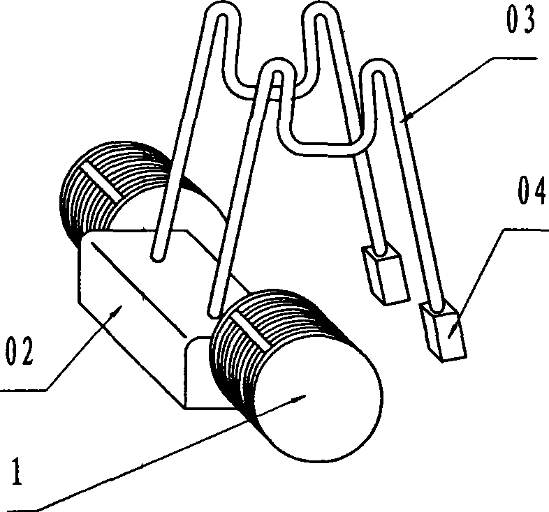
[0004] 1. The frame adopts spring steel wire 03, which has poor stability and is prone to deformation, resulting in changes in the position of the entire devi

Method used


Image

  • Cable-spun device of ring spinning frame
  • Cable-spun device of ring spinning frame
  • Cable-spun device of ring spinning frame

Examples


Embodiment Construction

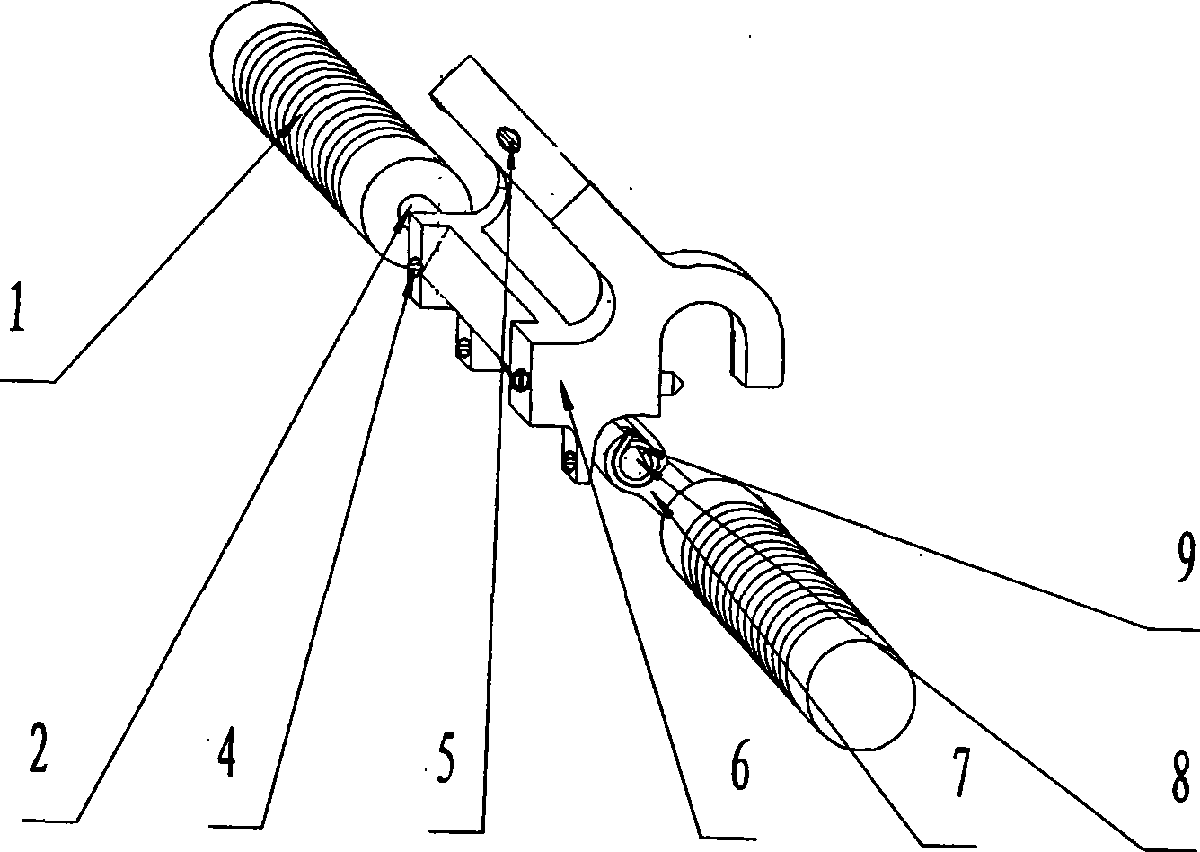
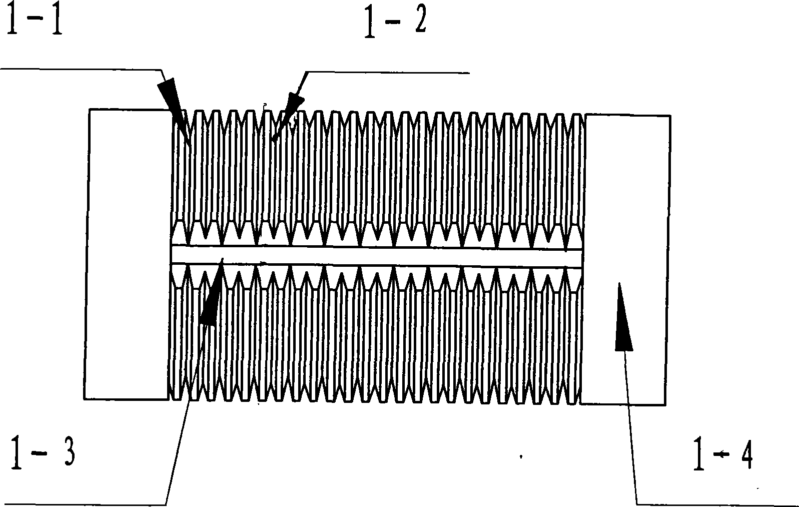
[0026] see Figure 2~4 As shown, the overall structure of the cable spinning device includes a splitting wheel 1, splitting wheel shaft 2, front top roller 3 of ring spinning frame, set screw 4, positioning screw 5, fixing clip 6, swing seat 7, swing seat shaft 8, Torsion spring 9, front roller 10 of ring spinning frame, front top roller shaft 11 of ring spinning frame and front top roller claw 12 of ring spinning frame. Wherein, the splitting wheel 1 includes a deep splitting groove 1-1, a shallow splitting groove 1-2, a transition section 1-3 and a splitting wheel base 1-4.

[0027] During spinning, buckle the hook of the fixing clip 6 on the front top roller shaft 11 of the ring spinning frame, at this time, the set screw 5 on the fixing clip 6 is naturally above the front top roller claw 12 of the ring spinning frame, tighten The set screw 4 ensures that the fixing clip 6 reliably clamps the front top roller shaft 11 of the ring spinning frame. According to the needs of ...


PUM


Abstract

The invention discloses a solospun device of a ring spinner in the textile industry, which comprises a fixation clamp which is buckled on a front leather roll shaft of the ring spinner by a hook, and a partition wheel which is arranged at both sides of the fixation clamp and connected with a swing bearing. A shaft of the swing bearing is sheathed with a spring used for adjusting the tensile force of the swing bearing and the partition wheel closely fits to a front roller of the ring spinner and rotates with the rotation of the front roller by the action of a friction force. The fixation clamp is also fixed above a jaw of the front leather roll shaft by a locating screw and fixedly held on the front leather roll shaft by a holding screw to form a three-point fix. The surface of the partition wheel is provided with a partition groove with deep and shallow sections as well as wide and narrow sections which are alternated with each other and a transition section vertical to the partition groove while the transition section is a groove of which the bottom is flush to the bottom of the deep section of the partition groove. The solospun device has the advantages that the fixation clamp of the solospun device has stable rigidity, no frictional loss occurs between the fixation clamp and machine parts of the ring spinner, the partition wheel has reliable operation and the fiber can be prevented from accidental damages.

Description

technical field [0001] The invention relates to the technical field of ring spinning frame spinning in the textile industry, in particular to a novel cable-type spinning device, especially a cable-type spinning device used in worsted wool spinning and semi-worsted spinning systems. Background technique [0002] In traditional ring spinning machine spinning, one roving is spun into one spun yarn. Cable spinning is to divide a fed roving into two or more fiber bundles, and each fiber bundle is spun Under the action of the yarn force, it rotates and twists around its own axis, and then all the divided fiber bundles with a certain twist converge together, and then twist around the axis of the yarn to form a strand of yarn. [0003] Chinese Patent No. ZL02264848.8 is a utility model patent for a cable-type spinning device proposed by the applicant of the present invention, which is mainly composed of a split wheel and a support (see attached figure 1 ), including the cage 02, th...

Claims


Application Information

Patent Timeline
IPC IPC(8): D01H7/00D01H7/02
Inventor 何春泉方磊兰红艳
Owner SHANGHAI TEXTILE GRP DETECTION STANDARD CO LTD
Learn More