Vacuum housing for a magnetic resonance apparatus

a vacuum housing and magnetic resonance technology, applied in the direction of superconducting magnets/coils, instruments, magnetic bodies, etc., can solve the problems of difficult handling, adversely affecting the geometry of the vacuum housing, and simplifying the leading

Inactive Publication Date: 2008-12-23
SIEMENS HEALTHCARE GMBH
View PDF8 Cites 4 Cited by
  • Summary
  • Abstract
  • Description
  • Claims
  • Application Information

AI Technical Summary

Benefits of technology

[0006]One advantage of the vacuum housing according to the invention is that it simplifies the leading through under a vacuum of bulky structural components, in that it decouples the size of the recess required by the dimensions of the first structural component from the size of the cover plate assigned to the first structural component. On the one hand this makes it simpler to handle, e.g. fit or change, bulky structural components, without on the other hand adversely affecting the geometry of the vacuum housing.
[0007]One example of a bulky structural component is a gradient line for example, on which significant forces act due to the large currents in the magnetic field. As a result it is very rigid and stable. The gradient line connects a gradient coil via the lead-through module to an electric contact of a power supply, arranged outside the vacuum chamber. It can have a length of more than 1 m and its form is tailored to the spatial conditions. For example it can run along a radial line from the lead-through module to the gradient coil within the vacuum chamber, while outside the vacuum chamber its form is such that it can be connected to a contact even if said contact is arranged at a different azimuthal angle. Being a largely inflexible line, it has dimensions that make it difficult to handle. With the aid of the invention it can be fitted or removed easily.
[0008]In a particularly advantageous development of the vacuum housing the second cover plate is part of a second lead-through module. This has the advantage that the size of the recess, as required due to the structural components to feed lead wires in and out through the recess, can be used for further lead wires to elements inside the vacuum housing.
[0009]In a particularly advantageous development, the second lead-through module comprises a drawer-type lead unit. This makes it possible to lead for example a high-frequency, temperature signal line and / or a shim control line such that the electric line can be connected electrically to a plug connector for example, having been led even to a region that is difficult to access due to the geometry of the MR apparatus and being inspected there.

Problems solved by technology

Being a largely inflexible line, it has dimensions that make it difficult to handle.

Method used


Image

  • Vacuum housing for a magnetic resonance apparatus
  • Vacuum housing for a magnetic resonance apparatus
  • Vacuum housing for a magnetic resonance apparatus

Examples


Embodiment Construction

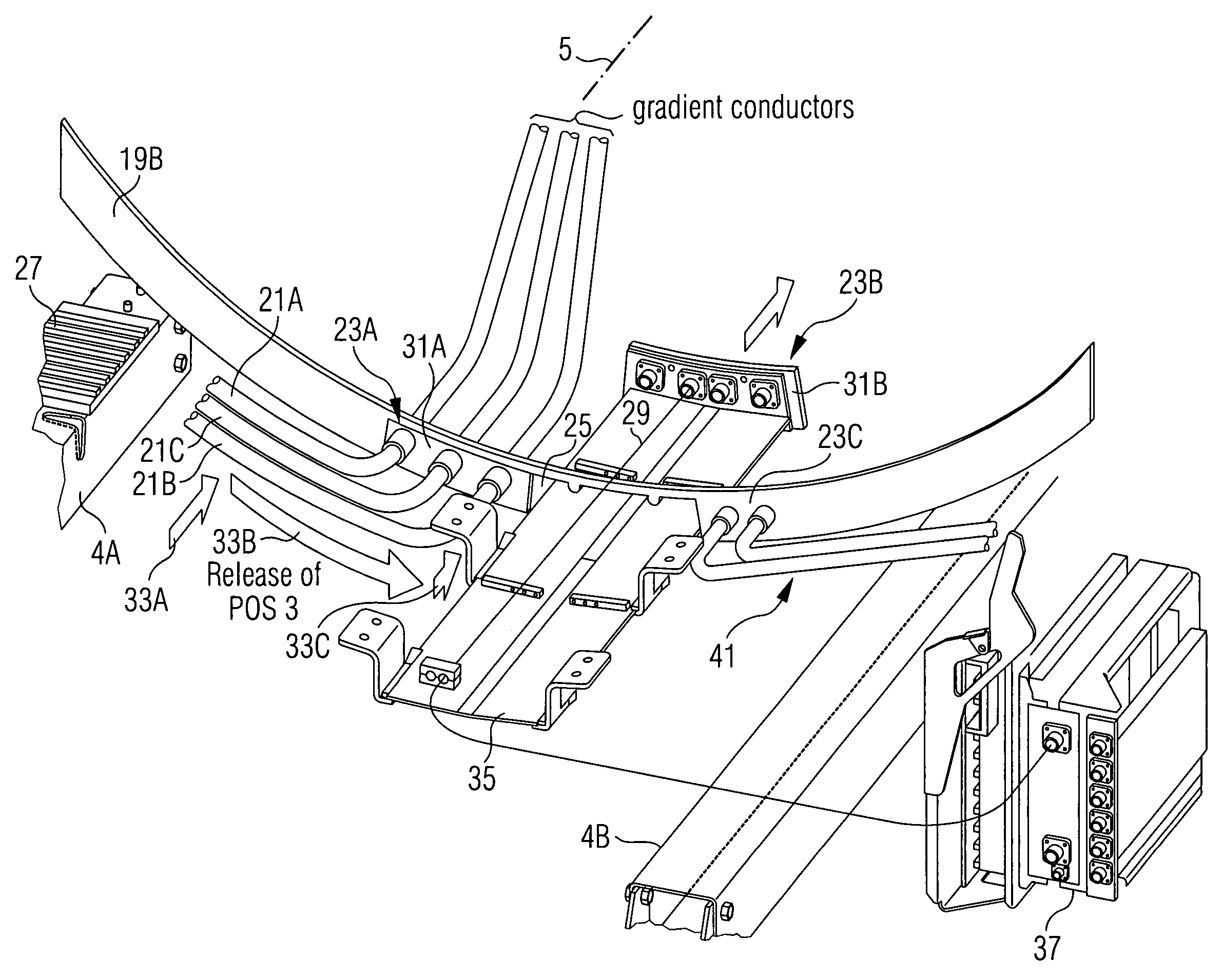
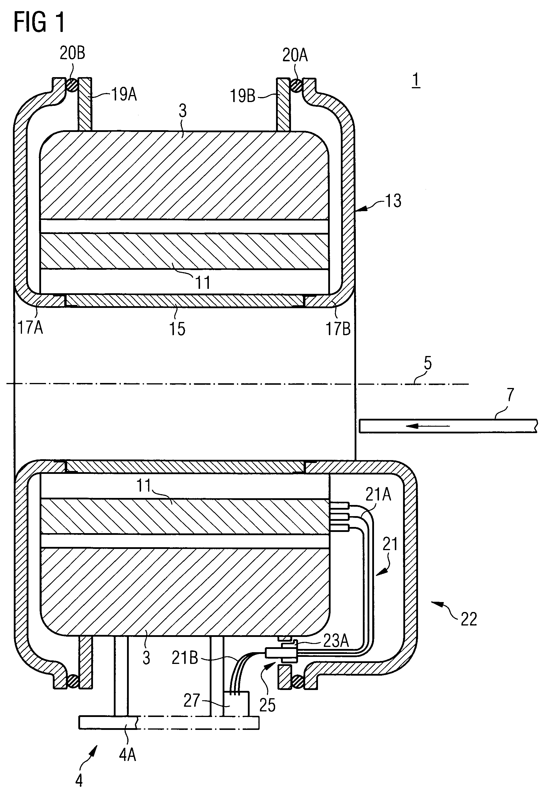
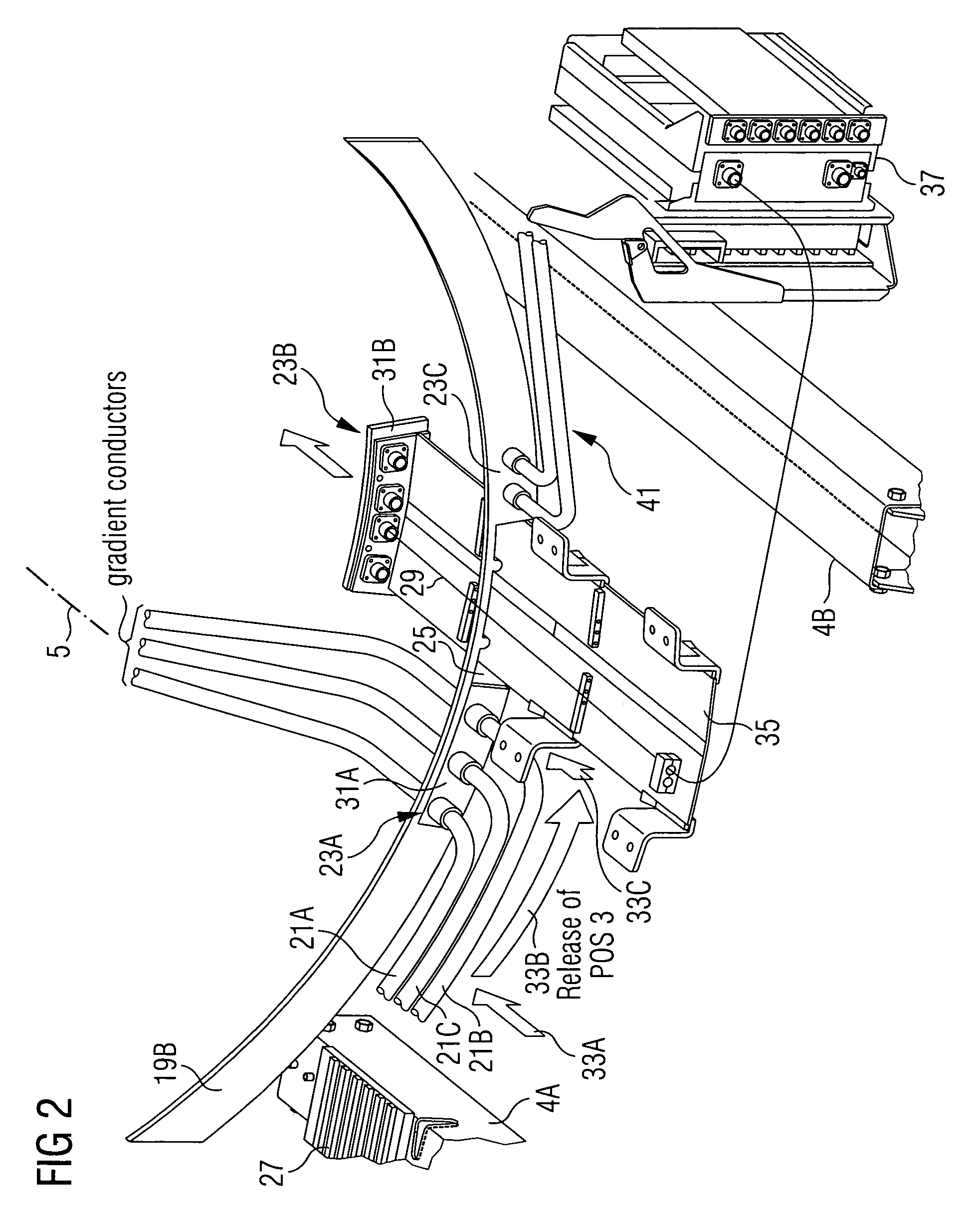
[0014]FIG. 1 shows a schematic diagram of a section through a magnetic resonance apparatus 1 with a cylindrical basic field magnet 3. The magnetic resonance apparatus 1 is fixed to the ground using a stable mount 4, which for example comprises two parallel supports 4A. The principal magnetic axis 5 corresponds to the axis of symmetry of the cylinder of the basic field magnet 3. A patient can be inserted into the examination area 9 of the magnetic resonance apparatus 1 with the aid of a patient support 7. Large magnetic fields are required in the examination area 9 for the magnetic resonance examination. These are modified by gradient magnetic fields from the gradient coil units 11 to allow imaging with local resolution. The strength of the basic magnetic field, the gradient current intensity and the ramp time of the gradient currents are of significance for image quality.

[0015]Because of the large currents in the gradient coils 11 in the prevailing magnetic field of the basic field ...


PUM

PropertyMeasurementUnit
current intensitiesaaaaaaaaaa
lengthaaaaaaaaaa
pressureaaaaaaaaaa

Abstract

Disclosed is a vacuum housing for a magnetic resonance apparatus having a recess for leading through lead wires to elements located inside the vacuum housing, and a first lead-through bushing module. The first lead-through bushing module is provided with a first closing plate which is configured so as to vacuum-tightly seal the recess along with a second closing plate. The first bushing module is also provided with a first structural component that is to be at least partially led through the recess during assembly of the lead-through bushing module and whose size defines a minimum size of the recess, which is greater than the size of the first closing plate.

Description

CROSS REFERENCE TO RELATED APPLICATIONS[0001]This application is the U.S. National Stage of International Application No. PCT / EP2005 / 050172, filed Jan. 17, 2005 and claims the benefit thereof. The International Application claims the benefits of German application No. 10 2004 004 294.2 DE filed Jan. 28, 2064, both of the applications are incorporated by reference herein in their entirety.FIELD OF INVENTION[0002]The invention relates to a vacuum housing for a magnetic resonance apparatus with a recess for leading through lead wires to elements inside the vacuum housing and with at least one first lead-through module.BACKGROUND OF INVENTION[0003]One approach to suppressing the noise generated during the operation of a magnetic resonance apparatus (MR apparatus) is to surround the largest possible part of the vibrating surfaces of the MR apparatus with a vacuum. To this end the MR apparatus is for example enclosed in an air-tight casing, where the pressure is approx. 100 mbar. The evac...

Claims


Application Information

Patent Timeline
Patent Type & Authority Patents(United States)
IPC IPC(8): G01V3/00G01R33/38G01R33/381G01R33/385H01F6/06
CPCG01R33/381G01R33/3854H01F6/065
Inventor EBERLEIN, EVASCHUSTER, JOHANNSTOCKER, STEFAN
Owner SIEMENS HEALTHCARE GMBH
Why Eureka
Try Eureka