
Dental handpiece

A hand-held, hands-on technology, applied in the fields of surgery, application, medical science, etc., can solve the problems of liquid entry, disinfection and sterilization effects, and achieve the effect of simple structure and high sensitivity

Inactive Publication Date: 2009-03-18
DURR DENTAL GMBH & CO KG
View PDF0 Cites 0 Cited by
  • Summary
  • Abstract
  • Description
  • Claims
  • Application Information

AI Technical Summary

Problems solved by technology

[0005] In the actuation switch of the handpiece there is always the risk of contaminated liquids entering the interior of the handpiece
While handpieces are sanitized or sterilized after each use, sanitization and sterilization can be compromised in hard-to-reach locations such as gaps

Method used


Image

  • Dental handpiece
  • Dental handpiece
  • Dental handpiece

Examples


Embodiment Construction

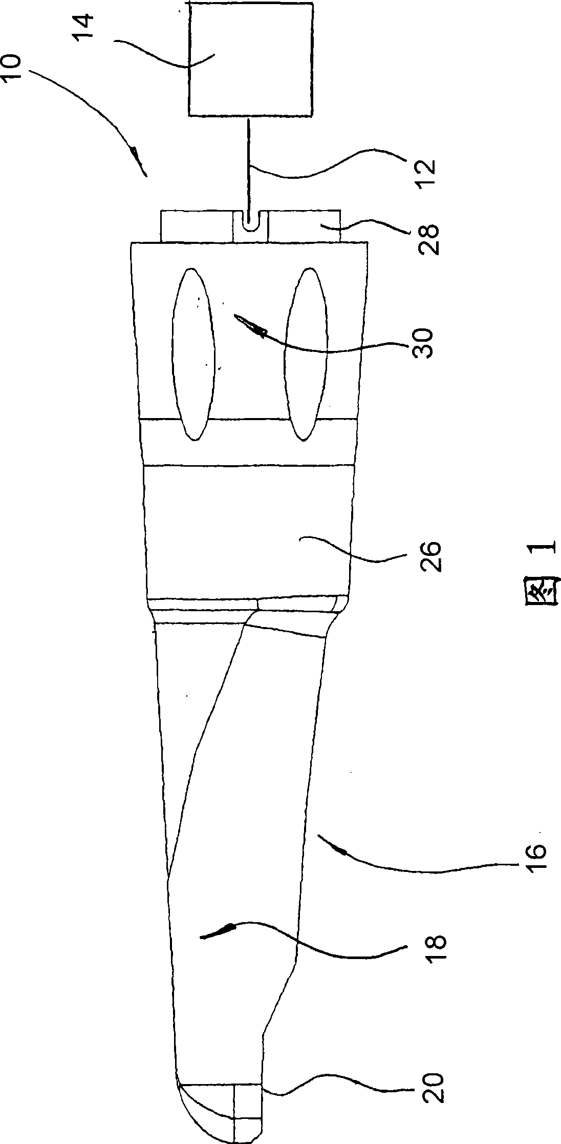
[0026] A dental speculum handpiece is generally indicated at 10 in FIG. 1 . The dental speculum handpiece is provided with an operating unit 14 via lines 12 only schematically indicated, which supplies the electronics (image converter and image preparer) contained in the speculum handpiece 10 with viewing light and supply voltage as well as acquisition and processing of the signals provided by the image converter of the scope.

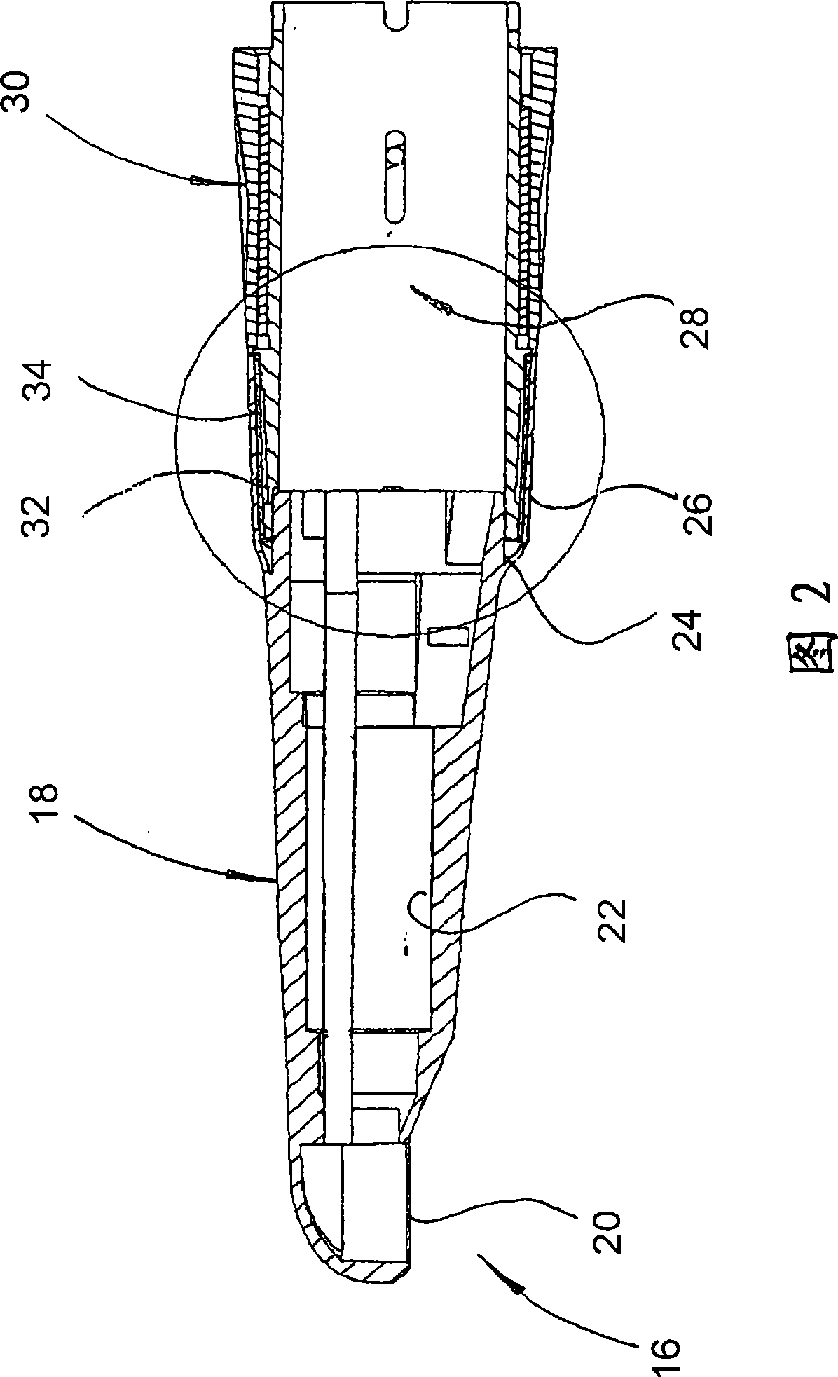
[0027] The scope handpiece 10 has a housing, generally indicated at 16 , which is an injection-molded plastic part. The housing 16 comprises a long front housing part 18 approximately in the shape of a slender cone and subdivided into stages on its inside in order to be able to receive the different optical elements and image converters at a given position. For the sake of clarity, these internal working elements of the sight glass are not shown in the figure. The transparent window 20 of the housing part 18 enables viewing into the oral cavity.

[...


PUM


Abstract

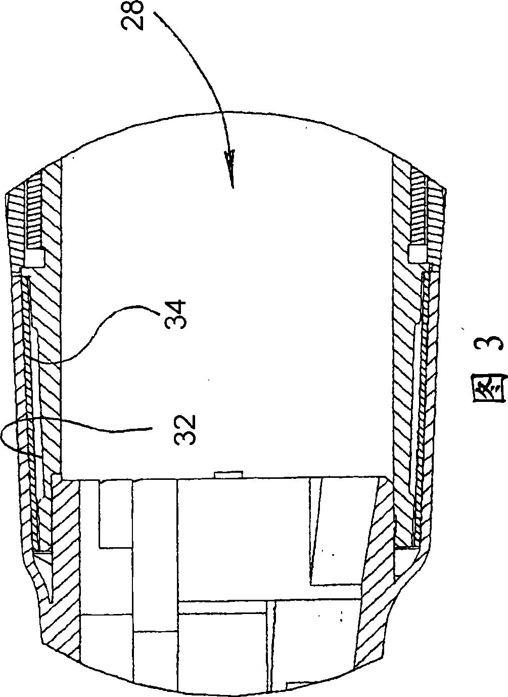
A dental handpiece, in particular a camera handpiece, has a housing (16), which is provided with a deformable wall portion (26) extending in the circumferential direction. Lying behind the deformable wall portion (26) there is a deformation sensor (34), which can be formed by a piezo film. The output signal of the deformation sensor (34) is monitored by a discriminator in such a way as to trigger the recording of an image when a predetermined deformation of the deformable wall portion (26) is reached.

Description

technical field [0001] The invention relates to a dental handpiece, in particular an intraoral camera / camera handpiece according to the preamble of claim 1 . Background technique [0002] Such handpieces are known with different internal working elements, such as turbine handpieces, ultrasonic handpieces, spray handpieces and speculum handpieces. [0003] Such handpieces often include control elements for controlling the operation of the handpiece, for example switches for controlling the sprayed liquid in spraying handpieces. [0004] To date, no operating elements have been provided on other handpieces. These handpieces are often controlled by foot switches. [0005] In the case of the actuating switch of the handpiece there is always the risk of contaminated liquid entering the interior of the handpiece. Although the handpiece is sanitized or sterilized after each use, the sanitization and sterilization can be compromised in inaccessible locations such as gaps. In add...

Claims


Application Information

Patent Timeline
Patent Type & Authority Applications(China)
IPC IPC(8): A61B1/24
CPCA61B19/5225A61B1/24A61B1/045A61B17/320016A61B90/37
Inventor P·莱斯R·迈尔
Owner DURR DENTAL GMBH & CO KG
Learn More