
Uniaxial tension loading unit for testing concrete carbonizing performance under tensile stress and testing method

A loading device and uniaxial stretching technology, applied in the direction of measuring devices, strength characteristics, instruments, etc., to achieve the effect of simple structure and convenient operation

Inactive Publication Date: 2009-03-18
SOUTHEAST UNIV
View PDF0 Cites 38 Cited by
  • Summary
  • Abstract
  • Description
  • Claims
  • Application Information

AI Technical Summary

Problems solved by technology

[0003] Aiming at the shortcomings existing in the prior art that it is difficult to couple concrete specimens under uniaxial tensile state and carbonation test, the present invention provides a uniaxial tensile test method and loading device for the carbonation performance of concrete under tensile stress , which can test the carbonation change law and influence mechanism of concrete specimens under continuous uniaxial tension

Method used


Image

  • Uniaxial tension loading unit for testing concrete carbonizing performance under tensile stress and testing method
  • Uniaxial tension loading unit for testing concrete carbonizing performance under tensile stress and testing method

Examples


Embodiment 1

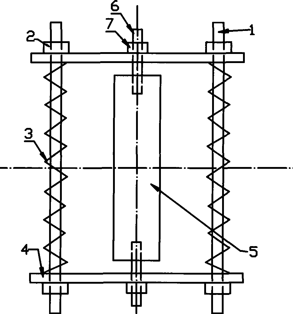
[0021] In the first step, a circular PVC pipe with a length of 300 mm and a diameter of 100 mm is used as a mold for making a concrete cylindrical specimen; The depth is 4cm. The concrete is formed by means of layered vibration, and the formwork is removed after one day of forming, and it is taken out after curing to the age required by the test.

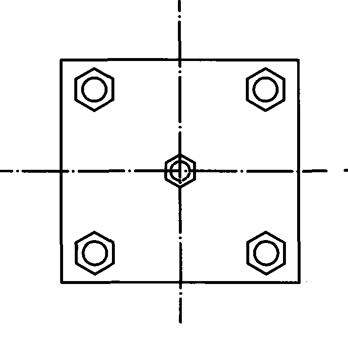
[0022] In the second step, four steel pipes are inserted into the four holes at the four corners of the lower steel plate, and four springs with the same characteristic parameters are placed on it, and the prepared cylindrical concrete specimen is placed on the lower steel plate, so that The pre-embedded bolts on the lower end surface of the concrete specimen pass through the hole at the central axis of the lower steel plate, and then put the upper steel plate on the same place, apply pressure to the spring to make the upper steel plate closely contact with the upper surface of the test piece, and tighten the steel plate at the four...

Embodiment 2

[0027] In the first step, a cuboid specimen is formed by a 100×100×300 cube triple mold. When forming, embed the embedded bolts at the central axis positions at both ends of the specimen, and the embedment depth is 7cm. Concrete is formed by layered vibration. The formwork is removed after one day of forming, and it is taken out after curing to the age required by the test. The curing age is determined according to different tests. Seal the two opposite faces and the upper and lower end faces of the cuboid specimen with epoxy resin, leaving only two opposite faces.

[0028] The second step, such as figure 1 and figure 2 As shown, four steel pipes are inserted into the four holes at the four corners of the lower steel plate, and four springs with the same characteristic parameters are placed on them, and the prepared rectangular concrete specimen is placed on the lower steel plate, so that the concrete The pre-embedded bolts on the lower end of the test piece pass through t...


PUM


Abstract

The invention discloses a single shaft tension loading device for testing the carbonation property of the concrete under tensile stress and a test method, wherein the hex nuts pre-embedded at the axis of two ends of the tested element connect the cylinder or rectangle tested element between two parallel steel plates, four same compressed springs are sheathed on four steel columns of the diameters smaller than the inner diameter of the springs, the two steel plates can parallel move between the four steel columns, the material parameters and the compressed quantity of the springs can be used to calculate the axial tensile load on the tested element, the tested element is axially patched with three stress sheets to find the actual tensile stress at different parts. The characteristic parameters of the springs can be changed to obtain the carbonation test parameters under different tensile stresses.

Description

technical field [0001] The invention relates to a concrete carbonation performance test method and a loading device thereof, in particular to a performance test capable of accelerating carbonization of a concrete specimen in a continuous uniaxial tension state under different tensile stress levels and its performance test method. test device. Background technique [0002] Concrete is a material that is inherently insufficient to work with cracks. There have been many studies on the deformation of its micro and mesostructure under the action of compressive stress, but the research on the characteristics of microstructure changes under the action of tensile stress is relatively limited. At present, the research on the tensile stress applied to concrete specimens is mainly realized through the device of bending stress, but there is no relevant report on the simple uniaxial tensile loading device. A key reason is that it is difficult to realize the uniaxial tensile state of con...

Claims


Application Information

Patent Timeline
IPC IPC(8): G01N33/38G01N3/00
Inventor 钱春香王辉巴明芳
Owner SOUTHEAST UNIV
Learn More