
Variable nozzle turbocharging control method and system

A technology of turbocharging and control methods, applied in electrical control, engine control, gas turbine devices, etc., can solve the problem of inability to continuously adjust the position of the nozzle section, difficulty in improving low-speed performance, and inability to provide supercharging pressure and air intake, etc. problem, to achieve the effect of increasing the intake air volume and output torque, increasing the feedback control speed, and improving the accuracy

Active Publication Date: 2009-03-18
BAIC GRP ORV CO LTD
View PDF0 Cites 40 Cited by
  • Summary
  • Abstract
  • Description
  • Claims
  • Application Information

AI Technical Summary

Problems solved by technology

The disadvantages of the fixed section turbocharger are: (1) When the engine is running at low speed, due to the little energy provided by the exhaust gas, the speed of the turbocharger is too low to provide suitable boost pressure and sufficient intake air volume , the engine cannot produce large low-speed torque, which makes it difficult to significantly improve its low-speed performance
(2) When the engine is running at high speed, the supercharger may overspeed due to the high exhaust temperature and pressure
(3) There is only aerodynamic connection between the supercharger and the engine, and the response lag of the supercharger is obvious during the acceleration process
The advantage of this mechanism is that the adjustment speed is fast, and the stepping motor can quickly move from the minimum position to the maximum position under the drive of the electric signal. The disadvantage is that the stepping motor advances in a single step and cannot continuously adjust the position of the nozzle section.

Method used


Image

  • Variable nozzle turbocharging control method and system
  • Variable nozzle turbocharging control method and system
  • Variable nozzle turbocharging control method and system

Examples


Embodiment Construction

[0041] The present invention will be further described below in conjunction with the accompanying drawings.

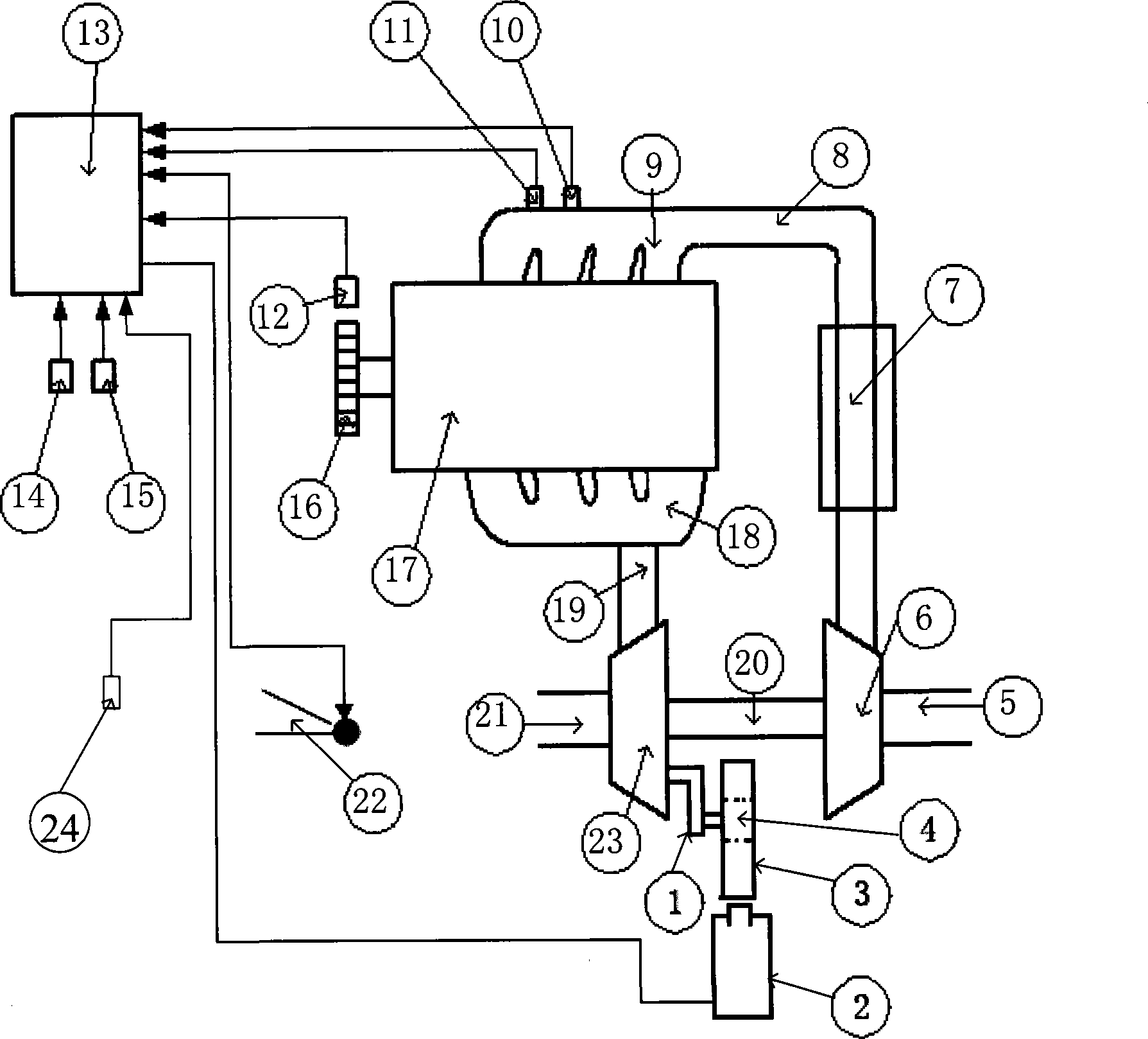
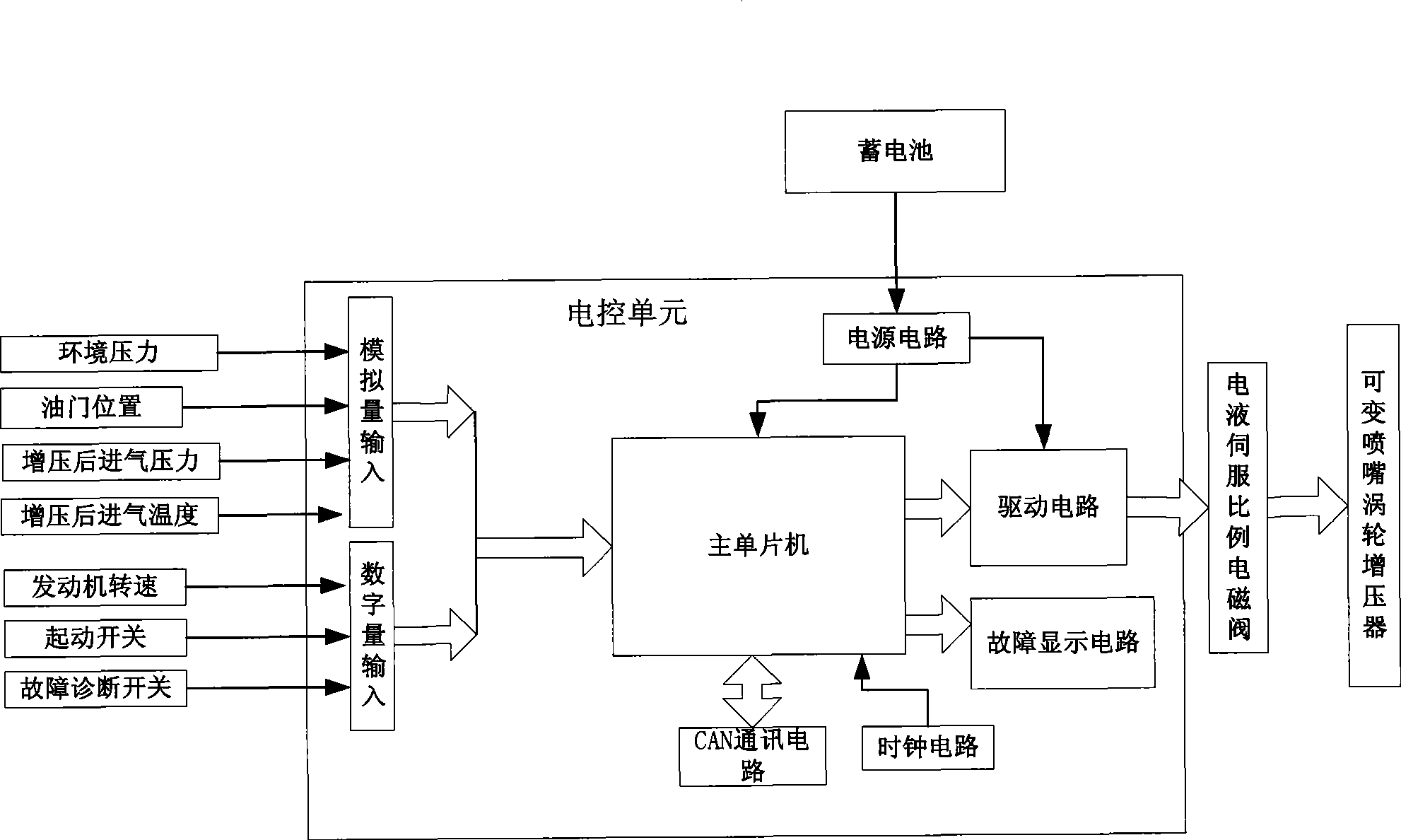
[0042] figure 1 It is a connection diagram of the supercharging system of the present invention. The control system includes a variable nozzle turbocharger, an electronic control unit 13, an electro-hydraulic servo proportional solenoid valve 2 for adjusting the opening of the turbine nozzle ring, an engine speed sensor 12, an accelerator pedal position sensor 22, and a boost pressure sensor 10 , intake air temperature sensor 11, atmospheric environment pressure sensor 24, start switch 14, fault diagnosis switch 15 and the program stored in advance in the single-chip microcomputer of electronic control unit. The engine speed sensor 12 is installed at the engine flywheel 16 for collecting engine speed signals. The engine accelerator position sensor 22 is installed on the accelerator pedal, and when the driver steps on the pedal, the sensor and the pedal rotate coaxial...


PUM


Abstract

The invention provides a control method and a system for nozzle changeable turbocharger, which relates to an electric control system of a nozzle changeable turbocharger with an electrohydraulic servo ratio electromagnetic valve as an executor. The invention is characterized in that based on the acquired rotate speed of an engine and the acquired position signal of an accelerator pedal, a target boost pressure value and a target position driving signal value are worked out; and a control algorithm of the PWM signal value used to drive the electrohydraulic servo valve adopts an open loop feedforward control with the optimum position of the electromagnetic valve as the a control target, and a closed loop digital PI feedback control with a boost pressure in an air inlet pipe as a control target. In order to improve the control precision and the response speed of the control system, the control parameters of the closed loop PI control is obtained by checking up a two-dimensional MAP graph according to the rotate speed signal of the engine and the position signal of the accelerator pedal. Compared with the prior pneumatic control system, the electric control system has quick control response speed; and, compared with the control system in which a step motor is used as the executor, the executor of the invention has the advantages of big output torque and high precision.

Description

technical field [0001] The invention relates to an engine variable nozzle turbocharger system, in particular to a diesel engine variable nozzle turbocharger system using an electro-hydraulic servo proportional solenoid valve as an actuator. Background technique [0002] The turbocharger should adapt to the engine's wide speed range. The disadvantages of the fixed section turbocharger are: (1) When the engine is running at low speed, due to the little energy provided by the exhaust gas, the speed of the turbocharger is too low to provide suitable boost pressure and sufficient intake air volume , the engine cannot produce a large low-speed torque, which makes it difficult to significantly improve its low-speed performance. (2) When the engine is running at high speed, the supercharger may overspeed due to the high exhaust temperature and pressure. (3) There is only aerodynamic connection between the supercharger and the engine, and the response lag of the supercharger is obv...

Claims


Application Information

Patent Timeline
IPC IPC(8): F02D43/00F02B37/24F02C6/12
CPCY02T10/144Y02T10/12
Inventor 王恩华夏胜枝叶子青
Owner BAIC GRP ORV CO LTD
Learn More