Multidimensional solar vacuum heat-collecting tube
A technology of vacuum heat collecting tubes and solar energy, applied in the field of heat exchange components, can solve the problems of further reduction in production costs, and achieve the effects of long heating time, low production costs and high thermal efficiency
- Summary
- Abstract
- Description
- Claims
- Application Information
AI Technical Summary
Problems solved by technology
Method used
Image
Examples
Embodiment 1
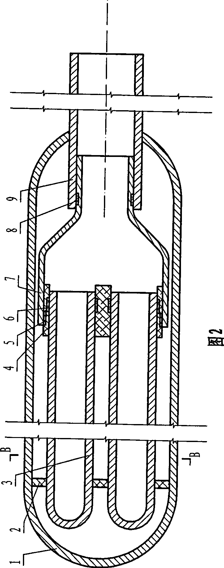
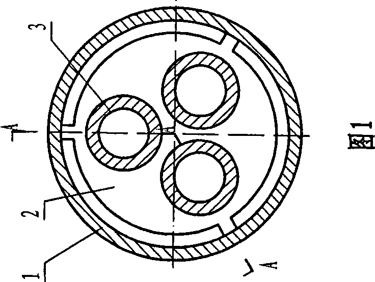
[0020] As shown in Figures 1 and 2, the multi-dimensional solar vacuum heat collection tube is composed of an outer tube 1, three inner tubes 3, a ring bracket 2, a cluster sleeve 4, a cluster head 7 and a casing 9, the inner tube 3 and the outer tube Tubes 1 are all blind tubes and are socketed in the same direction. An annular bracket 2 is arranged at the tail position in the outer tube 1, and three holes corresponding to the outer diameter of the inner tube 3 are evenly distributed on the annular bracket 2, and the tail ends of the inner tube 3 are respectively inserted in the corresponding holes on the annular bracket 2. A cluster sleeve 4 is provided at the front position in the outer tube 1, and the cluster sleeve 4 is provided with three through holes uniformly distributed in the shape of "pin", the diameter of which corresponds to the outer diameter of the inner tube 3, and the opening end of the inner tube 3 Inserted into the corresponding hole on the cluster sleeve 4...
Embodiment 2
[0022] As shown in Figure 3, the multi-dimensional solar vacuum heat collection tube is composed of an outer tube 1, three inner tubes 3, two cluster sleeves 4 and two cluster heads 7, the inner tube 3 and the outer tube 1 are all through tubes, and the inner tubes are 3 sets connected to the outer tube 1. Both sides of the inner tube 3 are provided with a cluster sleeve 4, and the cluster sleeve 4 is provided with three through holes uniformly distributed in the shape of "pin", the diameter of which corresponds to the outer diameter of the inner tube 3, and the inner tube 3 The open end is inserted in the corresponding hole on the cluster sleeve 4 and fixedly connected with glue. The cluster head 7 is cylindrical in shape with one end large and the other end small. The large end of the cluster head 7 is set on the cluster sleeve 4 and fixedly connected with the cluster sleeve 4 by gluing. The small end of the cluster head 7 is connected to the open end of the outer tube 1. w...
Embodiment 3
[0024] As shown in Figure 4, the multi-dimensional solar vacuum heat collection tube is composed of an outer tube 1, three inner tubes 3, a ring bracket 2, a cluster sleeve 4, a cluster head 7 and a sealing cover 10, the inner tube 3 and the outer tube 1 are both It is a blind pipe and socketed in the same direction. An annular bracket 2 is arranged at the tail position in the outer tube 1, and three holes corresponding to the outer diameter of the inner tube 3 are evenly distributed on the annular bracket 2, and the tail ends of the inner tube 3 are respectively inserted in the corresponding holes on the annular bracket 2. A cluster sleeve 4 is provided at the front position in the outer tube 1, and the cluster sleeve 4 is provided with three through holes uniformly distributed in the shape of "pin", the diameter of which corresponds to the outer diameter of the inner tube 3, and the opening end of the inner tube 3 Insert them into the corresponding holes on the cluster sleev...
PUM
 Abstract
Description
Claims
Application Information
 - R&D
- Intellectual Property
- Life Sciences
- Materials
- Tech Scout
- Unparalleled Data Quality
- Higher Quality Content
- 60% Fewer Hallucinations
Browse by: Latest US Patents, China's latest patents, Technical Efficacy Thesaurus, Application Domain, Technology Topic, Popular Technical Reports.
© 2025 PatSnap. All rights reserved.Legal|Privacy policy|Modern Slavery Act Transparency Statement|Sitemap|About US| Contact US: help@patsnap.com


