
Fastening element

一种紧固件、中间区的技术,应用在适用紧固件的手动工具、叠加层的镀覆、螺栓等方向,能够解决铬钢昂贵等问题

Inactive Publication Date: 2009-03-11
HILTI AG
View PDF1 Cites 11 Cited by
  • Summary
  • Abstract
  • Description
  • Claims
  • Application Information

AI Technical Summary

Problems solved by technology

[0007] The disadvantage of this workpiece is that stainless chrome steel is more expensive

Method used


Image

  • Fastening element
  • Fastening element
  • Fastening element

Examples


Embodiment Construction

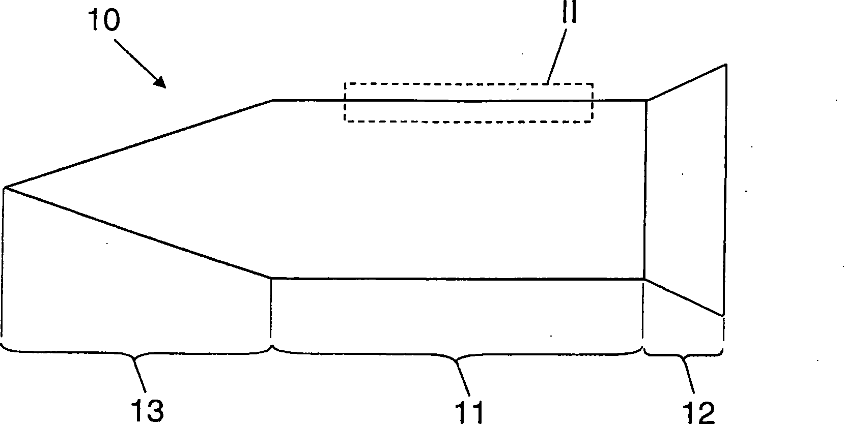
[0026] exist figure 1 and 2 A fastener 10 designed as a nail is shown in . This fastening element 10 has a shaft 11, at one end of which a nail head 12 is formed and at its other end a nail point 13 is formed. Depend on figure 2 As can be seen, the fastener 10 has a core region 14 comprised of a carbonaceous steel having a martensitic or bainitic structure having a hardness between about 30 and 62 HRC. At least in the region of the rod 11 , radially on the outside thereof, an edge region 17 is formed which consists of a first, not too hard, low-carbon steel which has been tempered with a first alloying element. The edge region 17 having a thickness DR between 0.001 mm and 1.0 mm in a direction perpendicular to the surface of the core region 14 has an austenitic structure. Here, the alloying element is a metal selected from the group Ni, Mn, Co, Al, Cr, V or Mo. Inside the edge zone 17, the concentration of alloying elements increases from the inside to the outside. In t...


PUM

PropertyMeasurementUnit
directional tensile yield strengthaaaaaaaaaa
strengthaaaaaaaaaa
hardnessaaaaaaaaaa

Abstract

The invention relates to a fastening element, such as a pin bolt or a nail, an anchor rod, a screw or a rivet. The fastening element is provided with a core area (14) formed of relatively hard carbon steel and an edge area (17) positioned outside the core area (14) and formed of first low-carbon austenitic steel refined by adding a first alloy element. In order to improve the fastening element, the invention has such suggestion that an intermediate area (15a) at least formed of second low-carbon steel is arranged between the core area (14) and the edge area (17), wherein the second low-carbon steel has lower rigidity than the steel of the core area (14).

Description

technical field [0001] The invention relates to a fastener of the type stated in the preamble of claim 1 . Background technique [0002] This kind of fasteners made of steel, especially high-strength steel, such as nails, pins, screws, anchor rods, etc., are used in fixing technology to fix objects on hard installation materials, such as concrete, metal or Rock, or used to connect objects to each other. For this purpose, these fasteners have a shaft with a first end, optionally ending in a pointed tip, and a head, optionally at the other end of the shaft, which is enlarged compared to the diameter of the shaft. The driving or fastening process takes place, for example, percussively, for example by means of a power-operated setting tool, or rotationally, for example by means of a screw tool, or in another suitable manner. [0003] The commonly used high-strength steel combines high tensile strength and high yield limit (from about >800MPa). Fasteners can therefore be ma...

Claims


Application Information

Patent Timeline
Patent Type & Authority Applications(China)
IPC IPC(8): F16B19/14
CPCC21D9/0093C23C28/023Y10S411/914F16B19/14C23C28/021Y10S411/901B32B15/011C23C26/00B32B15/01C23C28/00
Inventor G·费尔德T·卡门
Owner HILTI AG
Learn More