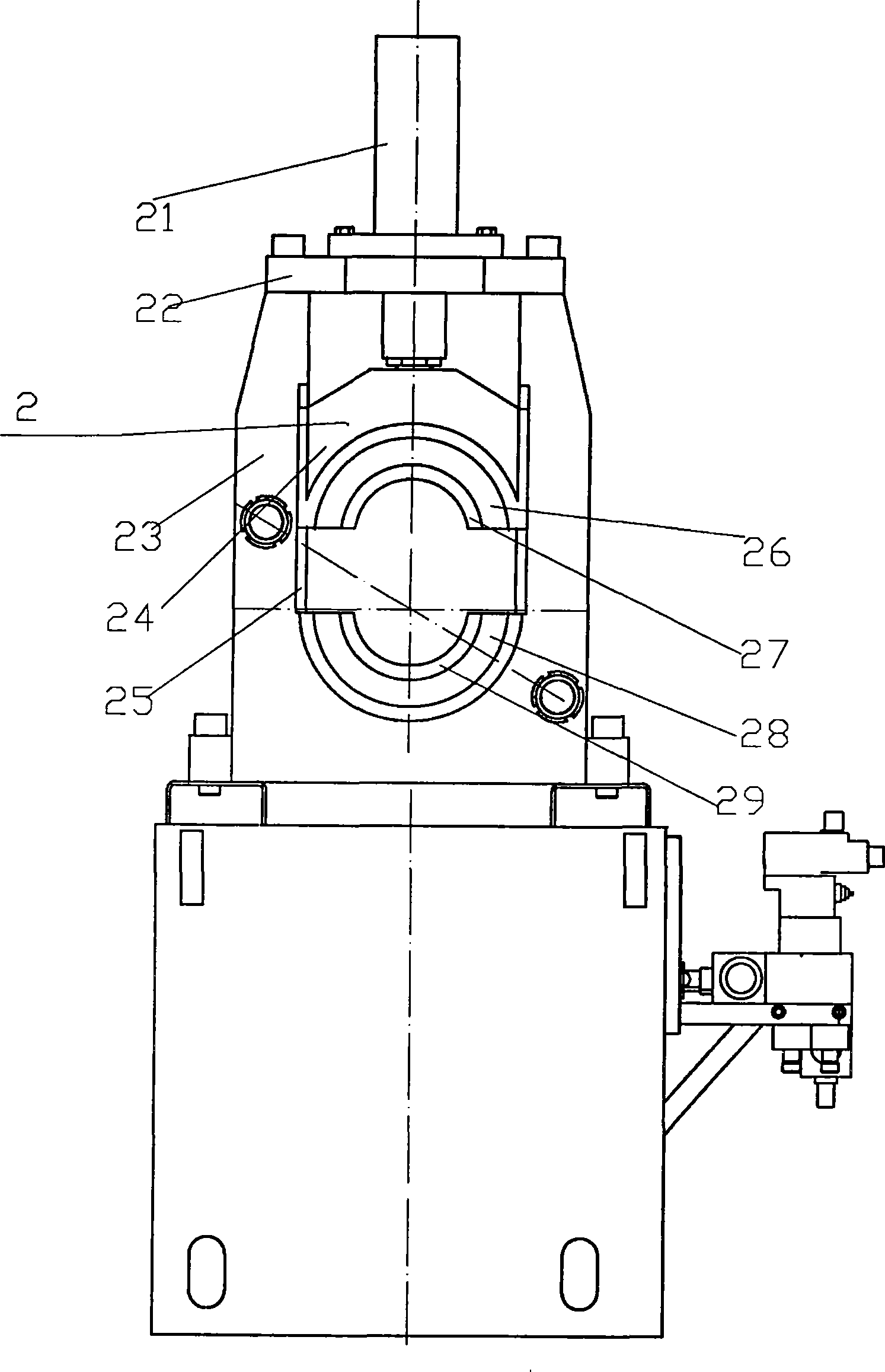
Pipe-end rotary extrusion expansion flanger
A technology of flanging machine and pipe end, which is applied in the field of pipe end spinning and flaring flanging machine, which can solve the problems of high energy consumption, poor finish, and many processing procedures
- Summary
- Abstract
- Description
- Claims
- Application Information
AI Technical Summary
Problems solved by technology
Method used
Image
Examples
Embodiment 1
[0041] Embodiment 1: Flaring and flanging are performed on the pipe end with a pipe diameter of 60 mm to form a 37-degree flanging. Install clamping jaws matching the outer diameter of the pipe to be processed on the clamping mechanism, send the pipe to be processed into the clamping mechanism, open the clamping oil cylinder, clamp and clamp the pipe, and reserve a flanging straight edge (as shown in Figure 4a); then install the spinning head on the propelling body, the specification of the spinning head is that the cone angle is 30 degrees, and the height is 100mm, and the jacking cylinder and hydraulic motor are turned on to carry out the jacking and spinning work (As shown in Figure 4b), the propulsion body drives the spinning head to contact the flanging straight edge reserved for the pipe body, and through the control valve group of the hydraulic mechanism, the jacking thrust is controlled to 25kN (kilonewton), and the spinning torque is 290N —meter (N—m), stop until the ...
Embodiment 2
[0042] Embodiment 2: Flaring and flanging are performed on the end of a pipe with a pipe diameter of 168 mm to form a 37-degree flanging. Install clamping jaws matching the outer diameter of the pipe to be processed on the clamping mechanism, send the pipe to be processed into the clamping mechanism, open the clamping oil cylinder, clamp and clamp the pipe, and reserve a flanging straight edge (As shown in Figure 5a); then install the spinning head on the propelling body, the specification of the spinning head is 30 degrees at the cone tip angle, and the height is 160mm, and the jacking cylinder and hydraulic motor are turned on to carry out the jacking and spinning work (As shown in Figure 5b), the propulsion body drives the spinning head to contact the flanged straight edge reserved for the pipe body, and through the control valve group of the hydraulic mechanism, the jacking thrust is controlled to 25kN (kilonewton), and the spinning torque is 290N —meter (N—m), stop until ...
Embodiment 3
[0043] Embodiment 3: Flaring and flanging the pipe end with a pipe diameter of 168 mm, forming a 90-degree flanging (as shown in FIG. 6 ). Send the pipe fittings to be processed into the clamping mechanism, open the clamping oil cylinder, clamp and clamp the pipe fittings, and reserve a straight edge for flanging, and first flang the pipe end at 37 degrees, as described in the first operation example; On the basis of completing the flanging at 37 degrees, replace the spinning head with a cone angle of 130 degrees and a height of about 140 mm to flang the pipe body at 37 degrees to 90 degrees. The operation process is as described in Example 1; The control valve group of the mechanism controls the jacking force up to 25kN (kilonewton), and the spinning torque is 290N-meter (N-m), until the end of the pipe body forms a 90-degree flanging, the machine stops.
PUM
| Property | Measurement | Unit |
|---|---|---|
| Angle | aaaaa | aaaaa |
| Length | aaaaa | aaaaa |
| Voltage rating | aaaaa | aaaaa |
Abstract
Description
Claims
Application Information
 - R&D
- Intellectual Property
- Life Sciences
- Materials
- Tech Scout
- Unparalleled Data Quality
- Higher Quality Content
- 60% Fewer Hallucinations
Browse by: Latest US Patents, China's latest patents, Technical Efficacy Thesaurus, Application Domain, Technology Topic, Popular Technical Reports.
© 2025 PatSnap. All rights reserved.Legal|Privacy policy|Modern Slavery Act Transparency Statement|Sitemap|About US| Contact US: help@patsnap.com


