Bleeder valve for pressurised furnace

A relief valve and valve seat technology, applied in the field of relief valves, can solve problems such as reducing pressure

Active Publication Date: 2009-03-04
PAUL WURTH SA
View PDF2 Cites 2 Cited by
  • Summary
  • Abstract
  • Description
  • Claims
  • Application Information

AI Technical Summary

Problems solved by technology

Although known closures with convex closure surfaces are preferred in terms of ease of closure due to their aerodynamic configuration, only a limited lifting force is allowed to be exerted on these closures and therefore only for a given valve diameter. Can reduce limited pressure

Method used


Image

  • Bleeder valve for pressurised furnace
  • Bleeder valve for pressurised furnace
  • Bleeder valve for pressurised furnace

Examples


Embodiment Construction

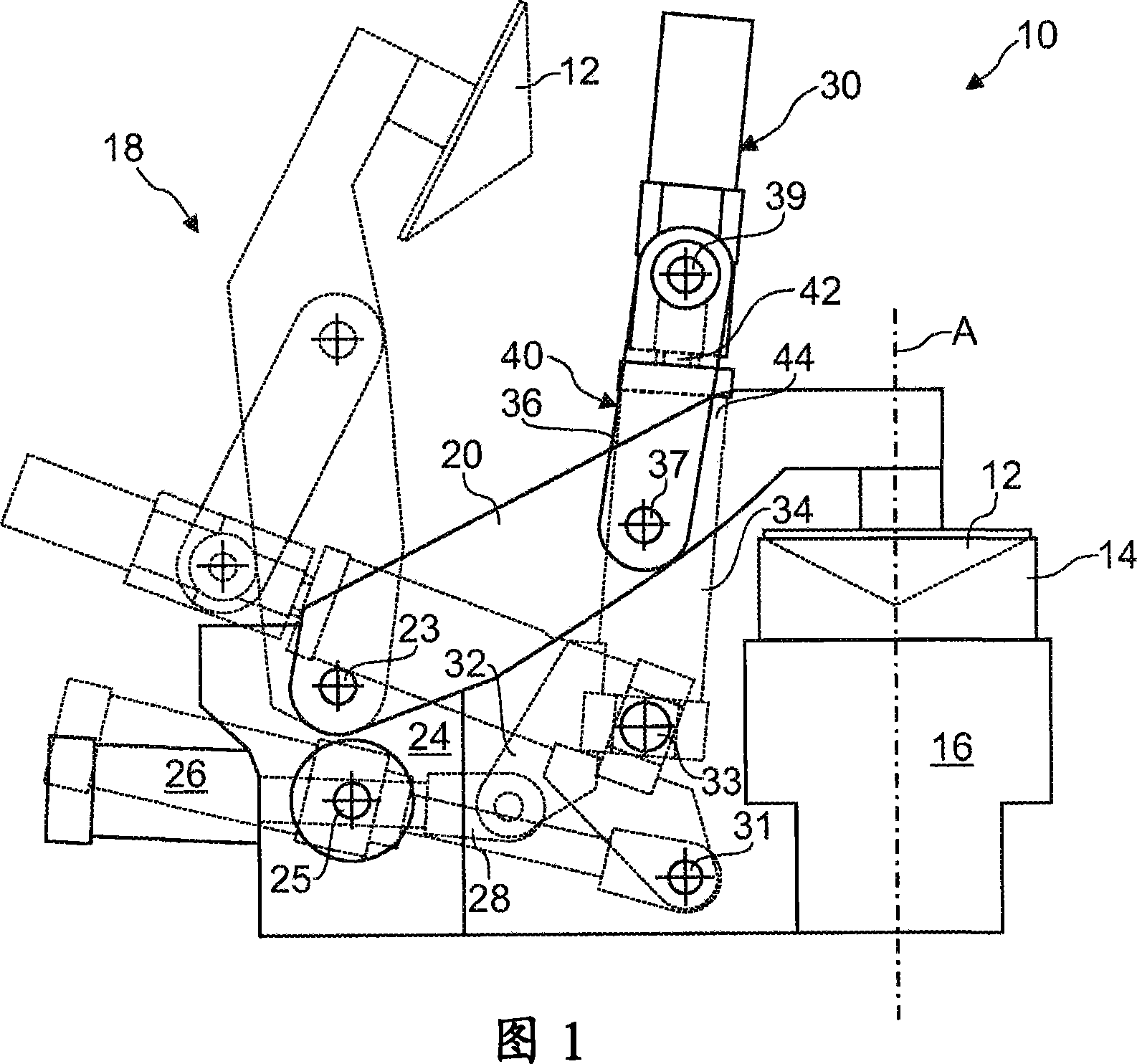
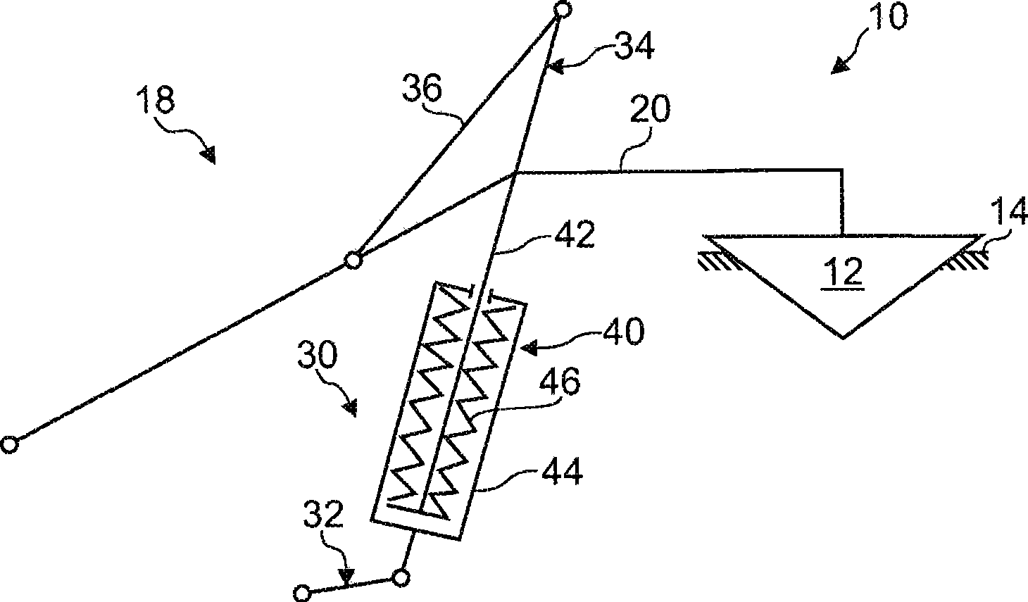
[0026] Figure 1 shows a relief valve (generally indicated by reference numeral 10) which is conventionally provided at the throat of a pressurized shaft furnace such as a blast furnace (not shown). The relief valve 10 includes a closure member 12 and a fixed valve seat 14 mounted coaxially on a discharge conduit 16 having a typical internal diameter of 400 mm to 1000 mm and communicating with the furnace throat. The relief valve 10 also includes an actuating mechanism (generally indicated by reference numeral 18) for switching between a closed position (shown in solid lines in FIG. 1 ) and an open position (shown in dashed lines in FIG. 1 ). Move the closing member 12 between.

[0027]The actuating mechanism 18 comprises a support arm 20 on a first end of which the closure member 12 is mounted by a ball and socket connection. A second end of the support arm 20 is pivotally connected to a fixed frame 24 by a shaft 23 for pivoting the shutter 12 between an open position and a c...


PUM


Abstract

A bleeder valve for controlling a gas outflow from the interior of a pressurized furnace to the ambient atmosphere through an exhaust conduit is proposed. The bleeder valve comprises a valve seat associated with the exhaust conduit, a movable closure member having a generally convex central closure surface and a peripheral sealing surface cooperating with the valve seat, and an actuating mechanism which is connected to the closure member for moving the closure member between a closed position on the valve seat and an open position distant from the valve seat. According to an important aspect, the closure member comprises a recurved deflection surface with an elevation angle between 30 to 70 degrees at the periphery of the peripheral sealing surface, the recurved deflection surface being shaped so as to impart to a gas outflow passing between the valve seat and the closure member a velocity component which is opposite to the initial opening movement of the closure member.

Description

technical field [0001] The present invention generally relates to relief valves for use in shaft furnaces, in particular blast furnaces, for controlling the outflow of gases from the interior of a pressurized shaft furnace to the surrounding environment. Background technique [0002] Depending on the furnace design, blast furnaces are typically operated at operating pressures in the range of 1-3 bar above atmospheric pressure. Relief valves (also known as pressure relief valves or explosion-proof valves) are usually installed on the throat of a blast furnace to control the flow of gases from the interior of the pressurized furnace through the exhaust duct to the surrounding environment. These valves reduce the pressure in the event that the pressure in the furnace exceeds a certain allowable value above the working pressure. These valves also serve as shutdown exhaust devices when the blast furnace is operating at low speed, they are used to ventilate the blast furnace. ...

Claims


Application Information

Patent Timeline
Patent Type & Authority Applications(China)
IPC IPC(8): C21B7/00F16K1/54C21B9/12
CPCF16K1/38Y10T137/7922C21B9/12F16K31/52C21B7/005F16K17/168F16K17/025C21B7/00F16K1/54
Inventor 埃米尔·洛纳尔迪利昂内尔·豪斯埃默尔卢特温·弗兰齐斯库斯
Owner PAUL WURTH SA
Why Eureka
Try Eureka